If you have an MGB and do some of your own maintenance, one of the tasks you probably do is adjusting the valve clearance. The valve adjustment is by the use of a .015" feeler gauge slipped between the valve stem and the nose of the rocker arm. One hand holds the feeler gauge, while the other hand holds a 1/2" wrench to loosen and hold the adjuster screw lock nut, and the third hand holds a screwdriver to turn the adjuster screw.
What? You don't have a third hand? Neither do I, so every time I run into this situation I am irritated by the clumsiness and potential inaccuracy of the entire process.
Recently the irritation and motivation to do something about it coincided, and I started thinking about a solution to the problem that required only two hands, while at the same time providing accuracy and repeatability.
The obvious alternative to the feeler gauge is the machinist's dial indicator, an acceptable version of which is available from many sources, including Harbor Freight, for between ten and twenty dollars, and sometimes on sale at less than that.
The advantage of the dial indicator is that the valve clearance can be read directly on the indicator face to .001" accuracy. The disadvantage is that the typical means of holding and positioning a dial indicator is through the use of an articulated magnetic stand. The magnetic stand is a devilish device, with multiple adjustments for locating and holding the indicator. The stand must be repositioned and readjusted for each valve, easily turning a 30-minute job into a all-afternoon ordeal. In other words, it's not worth the trouble.
In addition to the overall objectives of two-handed accuracy and repeatability, other objectives were to:
- Mount the dial indicator fixture quickly, without removing anything from the engine except the valve cover.
- Allow the indicator to be easily moved from one valve to the next without repositioning the fixture.
- Allow the unimpeded use of a wrench and screwdriver in valve adjustment.
- Fabricate the fixture at reasonable cost, using tools usually found in a moderately well-equipped enthusiast garage.
The dial indicator fixture described in this article meets these objectives, assuming you find a cost of $40 to $80 reasonable. The tools required to make the indicator fixture are all of the typical hand tool variety, with the exception of a drill press. A electric hand drill could be substituted, but might not yield the best results. Besides, it is a well-known truism that "He who dies with the most tools, wins", so this may be a good excuse to build your tool collection.
All of the development work for this fixture was done to fit the engine in my car, a 1964 MGB, with the original 18GA three-main bearing engine. I am not aware of any differences between my engine and other MGB engines that would affect the design of the fixture, but it is possible there could be some.
Materials List:
- 1/ea cheapo, 0-1" range, .001" dial indicator, Harbor Freight or equivalent, $10-20.
- 1/ ea 1" dial indicator stem extension (MSC, or other industrial supply house) < $5.00.
- 1/ea used MGB rocker arm, with bushing, $5-10 used, $25 new + bushing $5.00 + reaming cost of $?. Get a used one. When looking over used ones, pay attention to bushing condition. Minor scratches and gouges OK, but avoid ones that are worn off-center. Get two of them while you're at it.
- 1/ea used MGB rocker shaft, straight, moderately worn is acceptable, est. used price $10- 15. New price from Moss $25.00 , pt.#451-340, a bargain if no used part is available. Making one out of 5/8" shaft material will seriously complicate the project..
- 1/ea 1" x 36" x 1/8" thick weld-steel strap, from Lowe's or Home Depot, < $10
- 2/ea No.10 x 32 thread allen head set screw, 1/4" long
- 1/ea 3/8" x 1/2" long fine-thread bolt
- 1/ea 7/16" x 3/4" long fine-thread bolt
- 2/ea 5/16" fine thread nut
- 1/ea 3/8" flat washer
- 1/ea 7/16" flat washer

Dial indicator fixture project parts, with ruler for scale
The dial indicator fixture project is divided into four parts.
- Fabricating the bracket.
- Modifying the rocker shaft.
- Modifying the rocker arm.
- Assembling, mounting and using the fixture and dial indicator.
Part 1 - Fabricating the Bracket
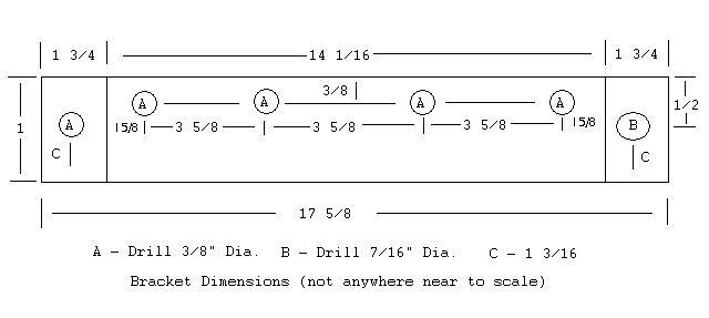
You will note that the bracket dimensions use fractional measurements, more like a woodcraft project than a metal craft project. I am assuming most prospective fabricators will not have an array of decimal inch calipers and micrometers, but probably will have a fractional inch tape measure. Secondly, the bracket itself doesn't require a great degree of precision in fabricating.
The bracket is made of 1/8" thick x 1" wide "weld metal" strap. A 36" piece will allow you to screw up one, and have enough left over to make another.
Note that the end bracket holes are different diameters. One end of an MGB rocker shaft is threaded at the factory for a 3/8" set screw. The other end is unthreaded, but the hole is too large to be threaded 3/8", and must be threaded 7/16". Therefore the bracket uses a 3/8" mounting bolt at one end, and a 7/16" at the other. These two holes are centered on the width of the bracket. Also note that dimension "C" is the distance from the end of the bracket to the centerline of the endmost holes.
The remaining four holes are NOT centered on the width of the bracket. They are offset slightly to one side, 3/8" from the edge. This offset allows the dial indicator to be perpendicular to the nose of the rocker arm when mounted. If the indicator is at an angle, accuracy will suffer.
Center punch the location of each hole so the drill bit will not wander.
When you have finished drilling the holes, place the strap in a vise at the vertical scribe lines. Using a large hammer, bend the 1 3/4" ends 90-degrees against the fixed jaw of the vise. The sharper the bend, the better.
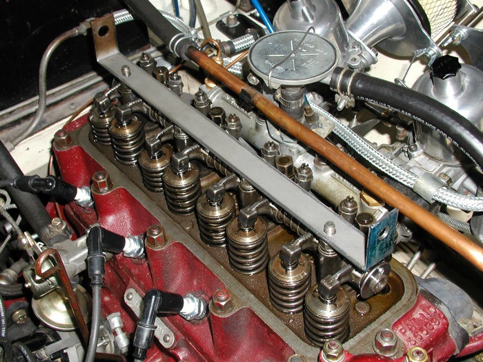
You should end up with a bracket that looks like the picture below. If the mounting holes do not exactly line up with the rocker pedestal studs, hopefully they will be close enough that you can take a round file and hog out the holes until it will fit.

Finished bracket mounted on rocker pedestal. Note offset mounting holes.
Referring to the fixture drawing, you may note that the individual measurements are 1/16" short of the overall length of 17 5/8". Get over it. If you can bend a foot-and-a-half long piece of metal in two places with a hammer within 1/16", you are a better blacksmith than I am anyway.

Part 2 - Modifying the Rocker Shaft
This is the easy part.
All you have to do is unscrew the slotted setscrew in the forward end of the shaft and remove the pressed-in plug from the other end. You will need a 1/4" or thereabouts diameter piece of metal rod about 15" long. Insert it in the rocker shaft from the end where you removed the setscrew. It will bottom against the pressed-in plug. Give the rod a whack with a hammer. It should pop the plug right out. If it doesn't, get a bigger hammer.
The end that had the plug is unthreaded and must be tapped with a 7/16 -20NF tap. You only need to tap it far enough for the bolt to hold, say 3/8" or so. Hacksaw the end off the 7/16 x 3/4" long fine thread bolt until you are left with a bolt with the threaded portion about 3/8" long. A 3/4" long bolt was specified because 7/16" bolts shorter than that are not commonly found in hardware stores.
That's it for the rocker shaft.
Part 3 - Modifying the Rocker Arm
Fun's over. This is the hard part. It is also the part of the project that must be done pretty close to perfectly to produce a fixture that yields acceptable results.
The dial indicator is mounted in a modified MGB rocker arm. In use, the modified rocker arm is turned around backwards, so the part of the rocker that was over the pushrod is now over the valve stem.
Step 1 - Remove the locknut from the adjuster screw. Clamp the rocker arm in the vise and hacksaw the ball off the end of the adjusting screw, then back the screw out of the rocker. Theoretically you should be able to screw the adjuster down out of the hole, however in actual practice the screw may bind up, perhaps due to thread distortion from the locknut.
Step 2 - The adjuster end of the rocker arm has an oil gallery that was plugged at the factory with a small, soft rivet. This rivet must be removed and the hole drilled and tapped for a 10-32 x 1/4" allen head set screw. This setscrew holds the indicator in the rocker. The head of the rivet can be easily seen on the end of the rocker arm. You must file the head of the rivet off, then use a punch to push it out from the top. It is actually easier than it sounds.
Drill out the gallery hole with a #21 drill bit. If you do not have a set of number bits, a 5/32" can be used. Tap the hole with the 10-32NF tap. If you used a 5/32" bit, be extra careful with the tap since the hole will be slightly undersize.
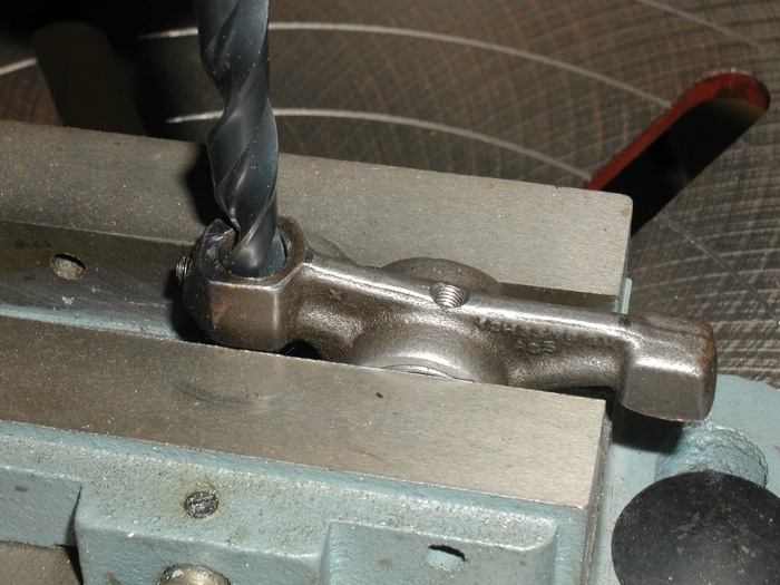
Step 3 - The adjuster screw hole must be drilled out to the diameter of the stem of the dial indicator, 0.375". This is a critical part of the rocker arm modification since the resultant hole must be very straight and uniform. It is advisable to use a NEW 3/8" drill bit for this procedure. Both flutes of the drill bit must be uniformly sharp or the bit will tend to pull towards whichever side is sharpest, yielding a hole which is both oversize and not straight. Fortunately the rocker arm material is not particularly hard, so standard high speed steel (HSS) drill bits are satisfactory. Use a single point bit, not the triple-point type. Drill press spindle speed should be about 800rpm. Once you have the hole drilled, you are probably going to have to run a Dremel 3/8" sanding bit through the hole to clean it up a little. When finished, the indicator stem should slide smoothly into the hole without binding.

Drilling out the rocker arm adjuster screw hole to fit the dial indicator stem. Note position of set screw hole.
Step 4 - The modified rocker is located and held in place on the shaft by a set screw which engages the oil hole(s). Since there is no conveniently located oil gallery hole in the rocker that can be enlarged to accommodate this set screw, we must make our own. The hole should be drilled in the center of the rocker arm "spine", at the lowest point of the shallow angle. Use a center punch to mark where to drill and to help keep the bit steady while you start drilling. Use the #21, or a 5/32", drill bit. The hole should be drilled perpendicular to the surface of the shaft. A little error is not hyper-critical since the shaft can be rotated slightly to compensate. Tap the hole with the 10-32NF tap.
Part 4 - Assembling, Mounting, and Using the Fixture and Indicator
Slide the indicator rocker on the shaft, then loosely bolt the shaft in the bracket. The indicator mounting hole should be on the side of the bracket with the offset rocker pedestal holes.
Mount the fixture on the engine. Install the set screw into the threaded hole in the spine of the rocker. Line up the set screw over one of the oil holes in the shaft, and screw it down until it locks into place. Rotate the shaft and rocker until the indicator hole is over the nose of one of the valves. Slide the indicator stem into the mounting hole until it bottoms, or nearly so. At this point, if you have not obtained a 1" indicator stem extension, you will discover that the end of the indicator is about 1/2" or so short of reaching the nose of the rocker arm. If you have obtained (or made) and installed the extension, lightly tighten the set screw to hold the indicator in place. You may have to rotate the modified rocker shaft slightly to line up the indicator stem exactly perpendicular to the rocker arm nose. Tighten the end bolts on the shaft.
That's it. You're ready to go. Follow the normal valve adjustment procedure specified in the MG service manual. Except, of course, that you no longer have to "feel" the valve clearance, it can be read directly on the dial indicator. The dial indicator can be rotated to face either side of the car, allowing valve adjustment from either side.

Finished dial indicator valve adjuster tool, mounted on engine rocker pedestals.


To save me the time of reverse engineering this tool,where can I find the "fixture drawing" refered to in Part 1.
thank you in advance,
David
http://www.ctci.org/gilsgarage/images/P&G-2.jpg
You could also probably get away with a one inch on and off dial indicator base with a
arm
http://littlemachineshop.com/Products/Images/480/480.3385.jpg
Dave
Thank you for your interest in my valve adjustment fixture.
I was aware of the existence of th P&G gapper, and of the magnetic indicator stand. The P&G failed in design objective #2, moving the indicator from valve to valve without repositioning the fixture. The magnetic indicator failed objective #1, mounting the fixture quickly. My perceived dissatisfaction with indicator stands was discussed in the paragraph preceding the listing of the design objectives.
The P&G device seemed to me to be intended for engines with stud mounted rockers, such as the small block Chevrolet. I am not aware that it is useable on a rocker shaft type engine, but perhaps it is.
Ron Shaw
valve adjustment and we pop the gapper on it and there is a slight variation in vacuum.
And once you use the p&g that vacuum gauge will sits rock solid and you will notice a
better idle a sure sign of no variation in settings on the rockers. Also the 300 model has
the ability to be used while engine is at 600 to 700 rpm idle so you can check it
dynamically and hold the maximum gap.
Being a machinist myself, I basically do the same thing.
However, use that 'Devilish' device called the mag base.
I may just have to make one these!
Thanks
Perry
As a machinist, I expect you can do without the drawing of the bracket, but if you would like to have it, post a response and I will send you one.
Regards,
Ron Shaw
The drawing would save me a bit of time.
I would appreciate the drawing.
Also, I noticed that you have a rather nice air filter set-up with
horns on your SUs. That's what I was considering doing on mine Where
did you get that setup?
Thanks
Perry
I have submitted the drawing to be added to the fixture article. I don't know when, or if, this will be done.
Send me an e-mail to my address below and I will send you a copy of the bracket drawing.
Ron Shaw
rs0255@aol.com
caught up on all the tech submissions.
Want to leave a comment or ask the owner a question?
Sign in or register a new account — it's free