
About 50% of the time, when folks have low heat output from the Smith's Heater in a British Car, they have a bad heater valve. The other 50% of problems seem to be divided between a bad thermostat, core, or clogged head passages or an anemic fan motor.
If you are contemplating a new valve after having checked out everything else, then try the things I mention below. I am not an expert on heating systems, but I am willing to share my experience with others. I don't think you can go too wrong in making sure the OEM valve you use is in good condition, but the experience of many other folks has indicated that even brand new OEM-type reproduction valves have their shortcomings.
These quality control issues are easily overcome for the moderately adventurous owner/mechanic, and I offer a good alternative which some of you might find more attractive. I hope you find something useful for getting you more heat in what follows.
Assuring Your Stock Heater Valve Works Properly
For those of you who have suffered the indignity of a cold drive in your MG in the winter, and frost on the INSIDE of your windshield, I think I may have at least a partial answer as to why some of our cars just don't seem to heat up very well at all.
I purchased a new reproduction OE valve for my MGB and in looking at it carefully before installation and measuring some openings, both for the hose and head connections, and internally, at the valve, I quickly came to the conclusion that the inner valve simply did not travel far enough to let in a sufficient amount of water. With dial caliper in hand, I determined that, as this unit came from the factory, the valve was only opening about 30% of its necessary travel to allow a full 100% flow from the head to the heater hose output! This could explain a lot.
So I decided to open up the assembly, carefully drilling out the pop-rivet that holds the upper mechanism from turning in relation to the lower body casting. Once done, I chucked the valve body in a vise and twisted the top loose from the casting. It came apart fairly easily, and I discovered a rather simple mechanism.

MGB Heater Valve Operation Diagram
The innards are indeed simple, and all that happens as we turn the knob on the dash is that a lever rides up or down a ramp and causes a center rod that has a spring loaded cup attached to its interior end to move away from or against an internal opening to the head connection. This small cup shaped closure device (valve shut) is what controls the flow or allows it to open.
It is spring loaded to keep it closed, but it is free to travel a short distance along the rod if forced and it is retained by a simple E-clip. If the E-clip is removed, and the cup moved back on the rod, the relationship of the cup to the rod can be adjusted by simply stacking a few very small washers between it and the clip.
By just adding washers, I was able to adjust the full closed to full open movement of the cup shaped valve enough to actually allow the full open area of the valve opening to equal or exceed that of the open area of the input holes from the head (which are the same size as the exit holes at the hose connection)
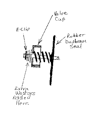
Adding washers to OEM MGB Heater Valve to increase flow rate
In theory, then, the flow of heated coolant should now be much better through the valve itself and should allow a significantly greater volume of coolant through the heater's core. That, I hoped, would increase the operating capacity of the core in relation to the outside air coming in, something which would greatly affect the efficiency of any heater.
As winter approached this year, I went ahead and replaced the old valve with my modified valve. Before beginning, I took some readings of the water temperature when fully warmed up, and of the air temp of both the outside air and the air delivered by the heater to the cockpit.
My initial results were as follows:
| Water Temp | Outside Air Temp | Heater Air Temp |
181 F |
74 F |
94 F |
After installing the modified valve, I got the following readings:
| Water Temp | Outside Air Temp | Heater Air Temp |
181 F |
74 F |
152 F |
As you can see, there was quite a difference between the two valves, verifying my original thesis that this valve might be a restriction and a major contributing factor to the heater's poor performance. After concluding the test for heater performance, I then shut the valve to observe if the modifications might have affected the Shut Off capabilities of the valve, however, they did not.
An interesting sidebar to all of this was my inspection of the old valve to see what its condition and operation was like. It had never delivered much heat, even when new and last winter, it was particularly anemic. I measured its full travel as it opened and closed, and sure enough, it too had only a small fraction of the needed travel to allow full flow. This one had only ever opened 20% at full open!
I know that some folks may not be willing to go this far in dealing with this situation, but this bit of research worked out very well. And, of course, I have described how to do it yourselves as explained above. If you have any questions, please leave a comment below.
Wishing you all a much warmer ride!
Something a little more reliable, but much less original...
Here's how to build an alternative heater valve for B-Series BMC engines.
You will need the following parts:
- Your old heater valve body (the lower, casting part)
- 1/4" pipe thread tap
- 1/4" tapered pipe thread reamer
- 7/16" metal twist drill
- 1/4" stubby brass pipe, nipples threaded both ends, about 1" total length
- 1 - 1/4" brass right angle connector elbow
- 1 - 1/4" brass bodied/stainless steel ball/ teflon sealed Ball Valve, lever type
- Flo-rite products, 150# WSP, 600# WOG, 172 8100 series
(their bar code tag shows the 17238170C, 1/4" FP Ball Vlv IPS), I.D. = 13/32" - 1 - Brass hose connection, 1/4" pipe threads on one end, and fit for 1/2" I.D. hose on the other end.
- Some Teflon pipe sealing tape orpaste to seal up all joints.
- A new heater valve to head gasket or make your own.
Step 1: Take the old heater valve, and cut off the base using a hacksaw. Cut it off right at the point where the base pedestal flares out into a funnel-shape. Be careful to cut it off as square as possible and then to file or grind off all rough burrs and edges. This will leave a pedestal that is about 1 1/4" high from the bottom of the mounting flange to where you will add the other components.
Step 2: You will next need a 1/4" pipe thread tap and a 7/16" drill bit for drilling out the interior passageway of the base to accomodate the tap. You are going to reuse the existing coolant passage but you have to drill it bigger first for the tap. You will find that it is easiest to drill this passageway if the base can be held in a vise on a drill press. If you don't have a drill press, just put the base in your bench vise or hold it with C-clamp and the drill should go through fairly easily. Just drill all the way through. When the drilling is done, finish the hole by reaming it with the tapered pipe thread reamer as this will prevent the base casting from fracturing and the pipe tap from binding when you attempt to thread it in the next operation.
Step 3: Tap the hole at least 1/2 way down using some lube as you cut the threads. When done, clean it all up good to clear away any shavings.
Step 4: Apply sealer and thread up one of the short double ended pipe nipples into the hole in the base.
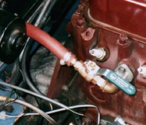
Step 5: Apply sealer to the other end of the nipple and run up the right angle connection over this nipple and tighten until the whole affair is in the base such that it fits the head mounting holes properly. You will want to bend the right angle elbow so that it is pointing up towards the water input hose fitting on the heater box. (see photo above) This will actually provide a smoother transition from the valve up to the heater core than the OE valve did. You can temporarily bolt the base to the head to do this fitting.
Step 6: Thread up the second short pipe nipple into the right angle connector with sealer.
Step 7: Now take the Ball Valve and run it onto that second nipple, after applying some thread sealer. Orient the valve so that the swing of the valve lever is towards the outside of the car, not towards the head. Tighten until the control lever comes out on top.
Step 8: Apply some sealer to the pipe threaded end of the hose adapter and turn it into the valve body to where it is good and tight without accidentaly turning the valve body around.
You are now done with making the alternative valve, just bolt the old pedestal base to the head with a new gasket, connect your hose, and off you go! You will find too that you now have better access to the distributor and there is far less chance that coolant will dribble into it.
This will give you a really good, long-lasting valve, tho you will have to operate it from the engine compartment. My next project here is to create a simple means to hold the control cable housing and connect the inner cable to this valve. If you beat me to it, let me know !
Bob Muenchausen (with many thanks to Les Bengtson) , © 2000

")


Want to leave a comment or ask the owner a question?
Sign in or register a new account — it's free