
MGB & GT Forum
Starter Relay Wiring
Posted by 2003JAG


 |
Topic Creator (OP)
Mar 2, 2012 07:03 PM
Joined 17 years ago
914 Posts
|
This is an old topic but I need help. I'm installing a new Lucas starter relay for the 80 MGB and need the correct wire placement for the black, brown, white/brown, and white/red wires for posts 30, 85, 86, and 87. The posts in the archives show every possible combination of wires to posts and none of them agree. Thanks.
Chuck
Chuck
 Georgetown, TX, USA
Sign in to contact
|
Mar 2, 2012 07:34 PM
Joined 14 years ago
3,505 Posts
|
 |
Mar 2, 2012 07:59 PM
Joined 16 years ago
1,652 Posts
|
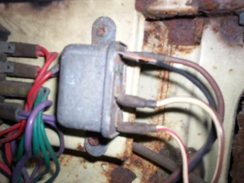
Chuck, I went to the garage and took photos and scribbled. Now, I keep forgeting which is the ignition and which the starter! For simplicity's sake, the first two pix are of the one closer to the front of the car (Relay 1); the next two of the one closer to the firewall (Relay 2).
1) Looking at the relay and and seeing the numbering, then moving the camera around to the wires. Assume the relay is mounted vertically (though mine is tilted a little): the terminal closest to the engine has the White/Brown wire attached; the terminal closest to the fender has the Brown wire; the terminal closer to the front of the car has the Black wire and the one closer to the rear has the White wires.
2) Assume the same vertical orientation: the terminal closest to the engine has the White/Brown wire (as above); the terminal closest to the fender has the Brown wire (as above); the terminal closer to the front of the car has the Black wire and the one closer to the rear has the Red/White wires.
Hope that helps; maybe a wizard will be along soon.
David
David J. Kinsey
Virginia Beach
Tidewater MG Classics
1980 MGB "Runaway"
Attachments:
P1070238.JPG 33 KB
|
|
Topic Creator (OP)
Mar 3, 2012 09:26 AM
Joined 17 years ago
914 Posts
|
Got this from FRM in PA. Very good information.
30 = load power in = N
87 = load power out = W/N
85 = control negative = (earth) = B
86 = control positive = (start signal) = W/R
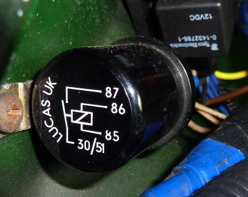
85 & 86 can usually be swapped, unless the relay has a diode in it(across coil); most don't - it will show on the diagram usually printed on the relay. If the diagram shows a resistor, polarity does not matter. But above is correct for neg earth system.
For that matter, 30 & 87 could be swapped too, but that is contrary to convention, and again, though rarely, some relays have quenching diodes across those terminals.
Chuck
30 = load power in = N
87 = load power out = W/N
85 = control negative = (earth) = B
86 = control positive = (start signal) = W/R
85 & 86 can usually be swapped, unless the relay has a diode in it(across coil); most don't - it will show on the diagram usually printed on the relay. If the diagram shows a resistor, polarity does not matter. But above is correct for neg earth system.
For that matter, 30 & 87 could be swapped too, but that is contrary to convention, and again, though rarely, some relays have quenching diodes across those terminals.
Chuck
 |
Mar 3, 2012 11:28 AM
Joined 22 years ago
11,366 Posts
|
|
Georgetown, TX, USA
Sign in to contact
|
Mar 7, 2012 07:25 AM
Joined 14 years ago
3,505 Posts
|
The 1970 uses the w1, w2 and c1, c2 terminals. The actuating coil is w1 and w2 which correspond to 86 and 85, respectively. The c1 and c2 correspond to 30 and 87, respectively.
They work the same, the coil is actuated by a small current and closes the large contacts to send power the the device, in this case the starter solenoid. This keeps the big current out of he little dash or ignition switch.
warmly,
dave
They work the same, the coil is actuated by a small current and closes the large contacts to send power the the device, in this case the starter solenoid. This keeps the big current out of he little dash or ignition switch.
warmly,
dave
Having trouble posting or changing forum settings?
Read the Forum Help (FAQ) or click Contact Support at the bottom of the page.
