1951 MGTD Front Disc Brake Modification
This modification uses the MGB front suspension and brake components and was fitted in conjunction with the OEM Girling front shock absorbers.
Note: Use the later MGB spring pan, which has facilities for mounting a front sway bar.
Use 1/2" SAE x 1-1/4" allen head cap screws for the sway bar link hole.
The areas that will require attention are as follows:
Tie-rod Rethreading and Shortening
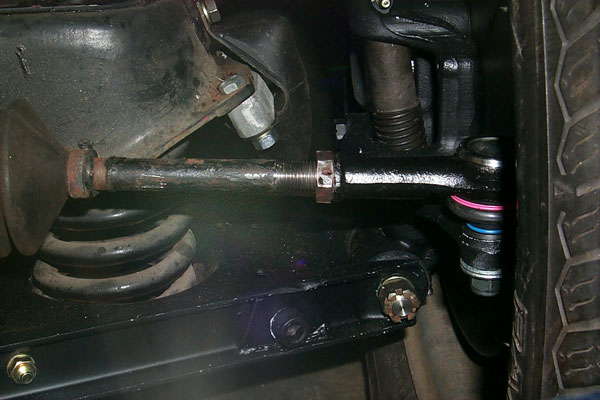
This operation necessitates that the tie-rod be rethreaded by 1-1/4" and then shortened by approximately 1". This can be carried out without disassembling the tie-rods from the steering rack, and can be done either before you completely dismantle the front end, or in the final stages of the conversion.
Remove the tie-rod end from the steering arm along with the jam nut. Now run a 9/16" x 16 TPI BSF hex die nut on to the threaded portion of the tie-rod. Refit the jam nut and tie-rod end to the tie-rod (the open shoulder of the jam nut should be approximately 1" from the end of the tie-rod). Reattach to the steering arm and lock the jam nut to the tie-rod end.
Using cutting fluid and a 12" adjustable wrench, rethread the tie-rod to an additional depth of 1-1/4". I ended up using an 18" adjustable wrench that I had. Use vise grips firmly attached to the tie-rod for greater stability.
With the shoulder of the jam nut as a guide, hacksaw thru the tie-rod. Remove tie-rod end and remove the cut off portion from within the tie-rod end. Run the hex die nut back off the tie-rod, which will clean up the end threads.
Install new tie-rod end, or use your original one. I used new tie-rod ends that were threaded to a depth of 1-1/4" for a total of 20 tpi.
I achieved the approximate toe-in by installing the tie-rod ends 16 complete turns each side. I now have plenty of thread to be able to get the correct alignment done.
Brake Line Fabrication
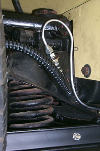
Fabricate new brake lines using the original BSF thread end fittings that install into the front brake line tee using Girling part number P4 female fitting (3/8" SAE) for the flexible brake hose connection. Use the MGB rubber-bumper model brake hoses.
Since my MGTD has had a MGB engine & transmission installed by the previous owner, it had separate master cylinders for the clutch & brakes.
Therefore, I did not have any issues with residual hydraulic pressure problems.
Upper Trunnion Bushings & Spacing Issues
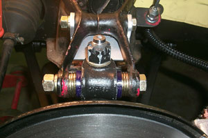
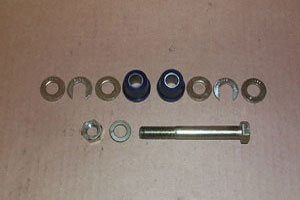
On the Girling shock absorber the inner distance between the shock arms at the trunnion end was 2.5". However, with the narrower MGB upper trunnion specifications, it will be necessary to add washers to each side of the trunnion bushings. The upper trunnion polyurethane bushings that I used were from superflex part SPF0282 (2). However, I found that the inner metal tube was too short (1.740") and the OD of the tube too large (0.630"). What this did was to distort the polyurethane bushings when the assembly was tightened. I had 2 new tubes made to 0.915" in length with a new OD of .600".
I used (3) 1/2" flat washers that were 0.105" thick with an OD of 1.050" on either side of the bushings, which worked out perfectly. However, I decided to slot 1 washer per side ahead of any necessary caster adjustments.
Bump Stop Plate Fabrication
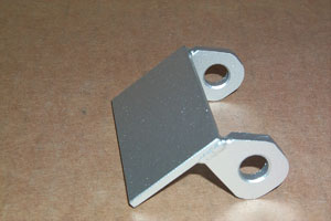
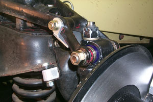
One of the issues that came up when using the MGB front suspension was figuring out how to incorporate a bump stop that will work in both compression & rebound modes.
I used the original replacement bump stops, and then fabricated a plate as shown in the images above. Simply made, using a 1/8" base plate 2-3/4" x 1-1/2" and (2) 1/8" plate side supports 1" x 7/8". Radius and trim the 1" portion of the supports. I then welded them to the base plate.
The tricky part is aligning and drilling the holes in the side supports. I drilled one before welding it to the plate, then I placed the plate into position, next I passed the largest drill I could thru the drilled side support and shock absorber arm assembly, thereby marking the location hole on the undrilled side support. I then removed the assembly and drilled the final appropriate size hole in the side support.
Road Wheel Alternatives (Non-Wire)
If you want to retain your original 5 hole pattern road wheels on your MG TD, then you must have 5/8" aluminum adaptors machined that attach to the MGB front hub.
Your alternative is to go with MGA road wheels, which will look slightly different than your original TD road wheels.
However, in my situation, this MG TD had already been converted to a later MGB rear axle and had the said above 5/8" thick adaptors (steel) fitted for use with the TD road wheels. Obviously, this increased the rear track width by an additional 1.5". I must admit that the rear end view of the car did look more masculine.
In my mind, using the late MGB rear axle with its 3.909:1 ratio over the MGTD stock ratio of 4.875:1 is a no brainer. Also, both the TD and the MGB use the same driveshaft pinion flange bolt patterns front and rear. However, this particular TD had been modified with a MGB engine and an all-synchro trans. The distance between the transmission flange and the rear axle flange was 28-3/4". Obviously, if you are using the original engine & transmission, this measurement could be different. See the technical library for MGB driveshaft lengths.
Originally I was going to remove the rear wheel adaptors and use MGA road wheels. In my haste, I purchased 5 MGA used road wheels. However, this was not going to be the cheapest route to go. In hindsight, I should have given this more thought because with the purchase and the shipping costs of the MGA wheels, I was in to over $200 to start with, and then came the chemical dipping of 2 of the MGA wheels at $99. I still would have had to straighten the rims (5) at a cost of around $100. Powder coating for 5 wheels would run around $325, plus an unknown dollar amount for a fabricated spare wheel adaptor to carry the MGA road wheel.
On top of this, with the axle being a MGB tube axle I would now need to remove the 5/8" spacer and fit 8 new wheel studs, though at a minimal cost.
OEM Road Wheels
The decision was made to cut my losses and stay with the original MGTD road wheels. all the 5 wheels were in good condition so I had no expenses there.
There were no expenses for a 4 stud spare wheel adaptor to be fabricated either.
However, heat treated aluminum wheel adaptors (2) & retaining nuts (8) had to be fabricated, which we will discuss next.
Aluminum Wheel Adaptors
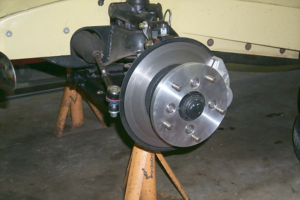
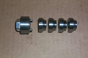
These 8" OD aluminum (6061T6) adaptors could have been made with a smaller OD (7.5"). However, this smaller OD size would not have resulted in much weight savings. The 8" dia adaptor weighed approximately 2.5 to 3 lbs, which included the 4 tapered securing nuts.
A clearer idea of the design of this adaptor and the 4 tapered securing nuts, along with the male pin driver, can be seen in the images below.
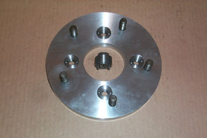
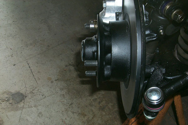
The installation of this adaptor requires that the MGB hub wheel mounting studs be shorten to prevent protrusion of the stud beyond the adaptor face. This is quite a simple job and can be accomplished with the hub fitted on the vehicle. See the image below for details.
Temporarily fit the aluminum adaptor to the hub. Measure the amount of stud protrusion on each stud beyond the adaptor face. Take the highest stud reading from the end of the stud to the face of the tapered nut. Remove the adaptor and install the correct amount of flat washers, along with a 1/2" SAE die nut that would be equal to, or slightly less, than this amount.
Tighten the die nut. This hardened 1/2" SAE die nut will act as a guide while you are cutting off the stud end and will ensure that the threads will be free run when you remove the die nut. Before removing the die nut file the new stud end flush.
I found it easier to have someone working the brake pedal while you are cutting off the studs; this allows the use of two hands.
Continuing... lubricate the hub studs and install the aluminum adaptor. Be sure to lubricate the tapered shoulder of the nuts. Using the special tool, tighten these nuts to 60-65 ft/lbs.
The 5 wheel mounting studs are the regular MGB front wheel lug mounting type 1/2" 20 SAE. However, depending upon how deep these studs have been pressed into the adaptor, a small unthreaded portion may protrude, thereby preventing the wheel nut from being fully tightened. to this end you should use a 33/64" drill bit and drill out several threads of the wheel nut, this will then allow the wheel nut taper to make proper contact when tightening the road wheel.
Unfortunately, the machine shop that made these aluminum adaptors for me simply copied the steel adaptors that I had, and made no detailed drawings or dimensions of the adaptor. Since the adaptors are now on the car, I would have to remove one of them, then, along with a tapered nut, have these computer copied onto a disc with the all the dimensions. So, if there are any MG TD owners out there interested in doing this, I would be more than ready to help them, however, I would require a nominal fee. I can be contacted by leaving a comment at the bottom of this article.
Wheel Nuts
Be sure that the wheel nuts that you use have sufficient taper contact between the wheel nut and the road wheel, use of the correct wheel nuts is essential. Obviously, the later MGTD (OEM) 1/2" SAE wheel nuts could be used but these are expensive. I was able to purchase some generic ones that produced the same amount of taper contact as the OEM style. The original 7/16" BSW wheel nut socket wrench worked fine.
Note: early MGB wheel nuts work just as well. However, they require a different size socket for their removal. This would require carrying two different size sockets to remove a road wheel and spare wheel.
Also, due to the interference between the lug nut end and the hub cap, the later MGB Rostyle wheel nut will not work.
Steering Wheel Alignment
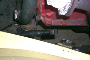
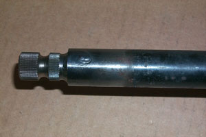
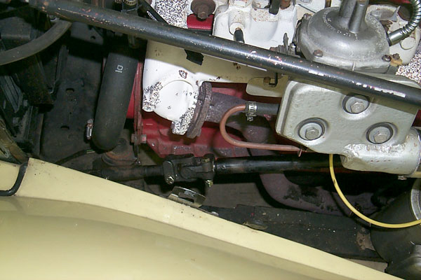
Fortunately, due to the fact that the previous owner had modified the steering shaft assembly (as seen in the following images), I was able to modify the shaft in such a way that it would only necessitate slight changes (if any) to the individual tie-rod lengths for centralizing the steering wheel.
The original steering shaft splined end only had one position for the pinch bolt like the steering rack pinion shaft (left image). I modified the steering shaft by cutting off the splined end of an old MGB steering pinion shaft, which has an annular groove around the splines, then cutting off the splined end of the original steering shaft. An adaptor bush was made and then both pieces welded with an additional plug weld (right image). A late MGB steering shaft universal joint complemented the final assembly (bottom image).
Tires
At the time of writing the availability of 165/80R15 tubeless tires were very limited. I was able to purchase a set (5) new tubeless Kumho Power Star 758 tires at a very reasonable price.
In closing, MGA Guru has a very good technical article regarding the use of tubeless tires with non tubeless wheel rims. Reading this will give you peace of mind before hitting the road.
Wheel Alignment
The measured wheel alignment of our MG TD before and after conversion:
| OEM Specifications | |
|---|---|
| Camber | 0 deg + or - 1 deg |
| Caster | 2 deg + or – 1/2 deg |
| Toe | Nil |
| After Conversion | ||
|---|---|---|
| Left Front | Right Front | |
| 0 deg | Camber | - 0.5 deg |
| 2.5 deg | Caster | 3.3 deg |
| 0.04" | Toe | 0.04" |
Although there was a slight difference in the caster readings from side to side, it was decided that if any adjustments were to be made they would be made subject to a road test first. On the subsequent road test I was quite happy with the way car handled and it was decided that no changes were necessary.
In conclusion, a very worthwhile conversion with responsive steering and brakes to match.


Your comments are very much appreciated
Doug
good, It is in fact, Brilliant, many thanks.
However it will remove the current, standard brake system Excitement of CAN I STOP!!!
Want to leave a comment or ask the owner a question?
Sign in or register a new account — it's free