
I'm happy to finally be able to share some tech information with a group who has always given me a ton of tech help. Thanks to everyone who gave me specs and advice to sort this out.
Apparently with a combination of new fuel tanks and new senders there's a bigger need to calibrate both gauge and sender than there used to be.
This is what you will need:
- Digital Multi-meter
- Resistors at the following values: 20 Ohms, 35 Ohms, 65 Ohms, 105 Ohms, 222 Ohms. Optionally you can just set the sender to these values.
- A 10VDC power source. Wall warts can do this and be found anywhere from RS to K-Mart.
- Needle nose or small pliers
- Patience!
When you have around 1/4 tank you can safely remove the sender without spilling gas. You can try to calibrate the sender first which is much easier than getting the gauge out. It might just be enough. You can also look at your gauge and take a reading off your sender while its in the tank and see how close it is to the corresponding values above. Or you can do pull the gauge and make sure its done the first time.
The following messages I'll go step by step with corresponding photos. First you can go to here go here if you want to build a box. For who just want to do it once, read this.
Barney helped me a great deal. I'm just doing what he shows here with different resistors. You can see everything clearly. What I'm posting shows you mainly how to do the sender and Barney's site shows you how to do the gauge.
Ok. When you pull your sender and air it out so you don't have a ton of gauge smell you will attach the probes of your DMM at the points shown below:
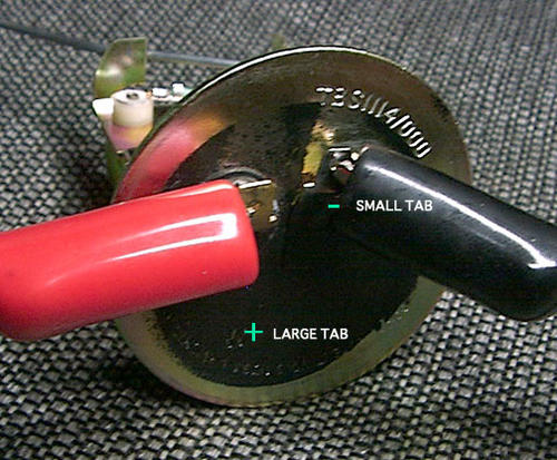
Attaching multimeter probes to fuel gauge sender
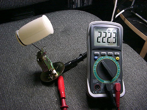
Below you will see the full tab stop and the empty tab stop. You need to swing the arm in each direction to its respective stop and bend each tab until you get 20 Ohms on the full side and 222 on the empty side. The full tab is pointed while the empty tab is rectangular.
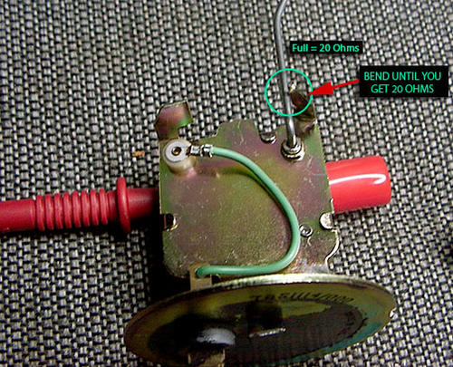
Bending fuel float arm stop tab, "full" position until multimeter reads 20 Ohms resistance
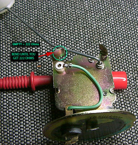
Bending fuel float arm stop tab, "empty" position until multimeter reads 222 Ohms resistance
What you're doing is calibrating the varible resistor which is the sending unit to hit the right values for full and empty like below.
If you are less than 20 Ohms on the full side you need to bend the tab flatter which will stop the arm sooner. If you are greated than 20 Ohms you bend the tab up letting the arm travel a bit more before stopping. Same for the empty.
Finally, its been suggested you bend the arm as a fix. NEVER bend the arm. You will throw it way out of alignment and nothing you do shown here will bring it back. The angle of the bend appears to be 20 degrees if you want to check it.
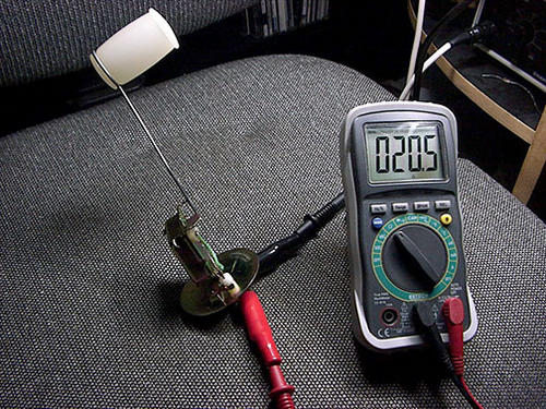
Correctly adjusted fuel gauge sender, full tank resistance reading
Correctly adjusted fuel gauge sender, empty tank resistance reading
Once you've fiddled your brains out and get close as you can you can, then get some fixed resistors in the values given above (20 and 222 Ohms, or use a single variable 1K ohm potentiometer and use your multimeter to calibrate it before attachment). Connect one side of the resistor to the gauge tab where the sender sends its signal, and the other end of the resistor grounded to the center bolt (see the diagram below).
Our gauges have somewhat crude adjustment points. As noted by another member this is a tin piece of metal, so get something that fits the slot completely so you don't bend it. Its moving on a rivet. It can be difficult to to finesse the adjustment but you'll get it with trail and error. Take your time and be careful.
Put your 10 VDC source on the other tab, and ground to the center bolt, then adjust calibration until the gauge needle lines up with the full or empty mark. Repeat the procedure for the opposite end of the gauge range. If you want to check the calibration of your gauge through the entire range of resistance values, you can cross reference the table below.
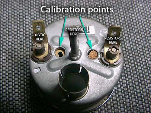
Calibration of fuel gauge, connect fixed resistor across terminals and apply test voltage
| Resistance | Tank Level |
|---|---|
| 20 Ω | Full |
| 35 Ω | 3/4 full |
| 65 Ω | 1/2 full |
| 105 Ω | 1/4 full |
| 222 Ω | Empty |

")


Want to leave a comment or ask the owner a question?
Sign in or register a new account — it's free