
I've owned my early 1980 MGB (built July, 1979) since it was a year old. Problems began to manifest in the electric circuit serving the fans not too long after I bought it.
First, at about 3 or 4 years, the "ice-cube" 30-amp circuit breaker in the fan circuit overheated and self-destructed. Unsuccessful in locating a replacement, I installed an in-line fuse holder and 30-amp glass fuse in its place.
The next problem was with the temperature switch mounted in the radiator that switches the fans on when the coolant was getting hot. The earlier style switch had two round pins and a unique mating connector on the wiring harness. The connector had overheated and corroded and lost conductivity. Again, I could find no replacement part, so I bypassed the switch, making the fans run continuously.
This resulted in several negative effects on the electrical system - straining the fan motors, the charging system and the wiring components serving the fans. That caused early failures of the ignition relay, the fuse and the fuse holder. Ultimately, one of the fan motors began to make a bit of bearing noise. Upon taking the motors out and disassembling them to try to oil the bearings, I found excessively worn bearings in both, plus one of the motors obviously had been very severely overheated.
Thanks to the B-Hive's web picture, I found that the late, improved radiator temperature switch for the later 1980 cars has universal spade connectors. For those of you who aren't familiar with the B-Hive, it's in Clemson, SC, run by an English gentleman, who gives you the best of service.
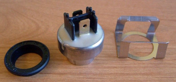
1980 MGB coolant temperature switch for radiator fan, grommet seal, and spring clip
I ordered the temp switch with the associated installation kit (grommet and spring clip), and two new fan motors. At Advance Auto Supply I bought two 30-amp relays, two 30-amp type ATC fuse holders, 10-amp fuses and some 14-guage insulated wire. I also bought an assortment of crimp-on wire connectors from Radio Shack.
The new relays were mounted near the existing ignition relay. They were set up to be controlled by the new temperature switch, through the ignition relay. This reduced load on the ignition relay. Next, by cutting the +12v wire to the driver-side fan motor at the passenger side connector in the wiring harness, I extended a separate wire for it back to one of the relays, and connected the passenger-side motor to the other relay through the existing wiring.
Each one of these circuits had one of the new fuse holders installed at the relay. Each of the new motors pulls a bit over 6 amps with the fan blades attached, so I am trying 10-amp fuses in the fuse holders.
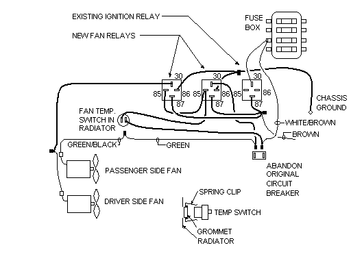
Wiring diagram for the addition of MGB radiator fan relay switches
Now, each fan has its own individual relay, individual fuse and individual wire, all much more lightly loaded than before. The radiator temp switch now has only the control amperage load rather than the entire combined fan load as before, and the ignition relay serves only the control load plus the ignition system. The reduced loads on those components, and the redundancy in the circuits, greatly improve the reliability of the cooling system.
P.S. - If you're converting to the late type temperature switch, be sure to install the grommet and spring clip as shown below, inserting the grommet into the clip, then inserting it into the radiator before pressing the switch into the grommet and seating it into the spring.

")


Want to leave a comment or ask the owner a question?
Sign in or register a new account — it's free