
MGB & GT Forum
Ignition Coil Wiring
Posted by EISNER62


|
Topic Creator (OP)
Aug 27, 2016 07:05 PM
Joined 10 years ago
48 Posts
|
|
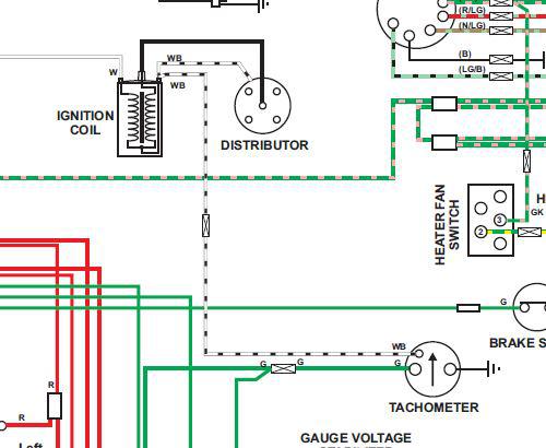
In the advance auto wire diagram for a 1974 MGB with 25D4 distributor and standard points/coil ignition, it shows a white wire from the fuse box to the coil on one side and two white/black wires on the other side of the coil going to the distributor and tachometer, which is the positive and which the negative? Couldn't find the answer using the search feature or a clear photo anywhere on line, and I have never been able to grasp basic stuff.
Thanks
Jeff
Thanks
Jeff

glbishop
Gary Bishop
|
Aug 27, 2016 07:09 PM
Top Contributor
Joined 14 years ago
2,926 Posts
|
|
Topic Creator (OP)
Aug 27, 2016 07:12 PM
Joined 10 years ago
48 Posts
|
|

naturbar
Buz Natur
Randleman, N.C., USA
Sign in to contact
1973 Chevrolet Nova "Drag Race...anyone ?"
1977 MG MGB "Her B For Me" 1978 Toyota Pickup "Black Beauty" |
Aug 27, 2016 07:13 PM
Joined 14 years ago
2,068 Posts
|
 Philly 'burbs, PA, USA
Sign in to contact
|
Aug 28, 2016 09:02 AM
Top Contributor
Joined 16 years ago
28,132 Posts
|
Jeffrey,
Perhaps it will help with a quick explanation of the ignition circuits for you.
The ignition primary circuit is the low voltage (12 volts) circuit that trigger the coil to fire. This 12 volts comes via the battery to the coil + terminal, through the coil windings, out the coil - terminal and on to the distributor. The points are a simple on/off switch. When the points close, they complete the primary circuit to ground, and when they open, they break the primary circuit. Since the points complete the primary circuit to ground, it makes sense that, in your negative ground car, the negative terminal of the coil should be connected to the points, which ultimately complete the circuit to ground. Correspondingly, in an early positive earth car, it is the positive terminal of the coil that is routed to the distributor and points, and on to ground.
A coil consists of two parts. One is a series of thousands of windings of very fine copper wire around an iron core. These windings start at the coil + terminal and exit via the coil - terminal, and on to the distributor and the points. When the points are closed, a magnetic field is generated around the coil's iron core, which becomes, in industry terms, "excited." When the points open and the primary circuit is interrupted, the magnetic field in the coil collapses and the coil shoots out a high voltage (perhaps 15,000 volts or so...) spark through the fat center wire. This spark travels into the top center of the distributor cap, through the rotor, and out through the appropriate distributor cap tower, through the spark plug wire, and on to the spark plug. This high tension circuit is referred to as the secondary ignition circuit.
What is often misunderstood is that it is when the points open, and the primary ignition circuit broken, that the coil fires its high tension spark, not when the points close.
Here's a factoid that may interest you. In our cars, we have four cylinders and each cylinder fires every other revolution, as is characteristic of a four stroke/four cycle engine. So at a hypothetical idle speed of 600 rpm (not necessarily realistic, but it makes for easy math...), that's ten revolutions per second. Ten times four cylinders is forty, divided by two since each cylinder fires every other revolution, means the coil must generate twenty sparks per second at idle. Thus the points must open and close twenty times per second. And this is just at a very slow idle speed.
At 6,000 rpm, ambitious but not impossible, and again for easy math, the engine is turning 100 times each second. Times four cylinders is 400, divided by two since each cylinder fires every other revolution, means that, at 6,000 rpm, the coil must make 200 sparks every second, and the points must open and close 200 times every second.
Food for thought...
Dick
Errabundi Saepe, Semper Certi
(Often wrong, but always certain)
Perhaps it will help with a quick explanation of the ignition circuits for you.
The ignition primary circuit is the low voltage (12 volts) circuit that trigger the coil to fire. This 12 volts comes via the battery to the coil + terminal, through the coil windings, out the coil - terminal and on to the distributor. The points are a simple on/off switch. When the points close, they complete the primary circuit to ground, and when they open, they break the primary circuit. Since the points complete the primary circuit to ground, it makes sense that, in your negative ground car, the negative terminal of the coil should be connected to the points, which ultimately complete the circuit to ground. Correspondingly, in an early positive earth car, it is the positive terminal of the coil that is routed to the distributor and points, and on to ground.
A coil consists of two parts. One is a series of thousands of windings of very fine copper wire around an iron core. These windings start at the coil + terminal and exit via the coil - terminal, and on to the distributor and the points. When the points are closed, a magnetic field is generated around the coil's iron core, which becomes, in industry terms, "excited." When the points open and the primary circuit is interrupted, the magnetic field in the coil collapses and the coil shoots out a high voltage (perhaps 15,000 volts or so...) spark through the fat center wire. This spark travels into the top center of the distributor cap, through the rotor, and out through the appropriate distributor cap tower, through the spark plug wire, and on to the spark plug. This high tension circuit is referred to as the secondary ignition circuit.
What is often misunderstood is that it is when the points open, and the primary ignition circuit broken, that the coil fires its high tension spark, not when the points close.
Here's a factoid that may interest you. In our cars, we have four cylinders and each cylinder fires every other revolution, as is characteristic of a four stroke/four cycle engine. So at a hypothetical idle speed of 600 rpm (not necessarily realistic, but it makes for easy math...), that's ten revolutions per second. Ten times four cylinders is forty, divided by two since each cylinder fires every other revolution, means the coil must generate twenty sparks per second at idle. Thus the points must open and close twenty times per second. And this is just at a very slow idle speed.
At 6,000 rpm, ambitious but not impossible, and again for easy math, the engine is turning 100 times each second. Times four cylinders is 400, divided by two since each cylinder fires every other revolution, means that, at 6,000 rpm, the coil must make 200 sparks every second, and the points must open and close 200 times every second.
Food for thought...
Dick
In reply to # 3342026 by EISNER62
In the advance auto wire diagram for a 1974 MGB with 25D4 distributor and standard points/coil ignition, it shows a white wire from the fuse box to the coil on one side and two white/black wires on the other side of the coil going to the distributor and tachometer, which is the positive and which the negative? Couldn't find the answer using the search feature or a clear photo anywhere on line, and I have never been able to grasp basic stuff.
Thanks
Jeff
Thanks
Jeff
Errabundi Saepe, Semper Certi
(Often wrong, but always certain)
|
Topic Creator (OP)
Aug 28, 2016 10:21 AM
Joined 10 years ago
48 Posts
|
|
Dick, Thanks, I printed that one off for my book and reference.
Last year I replaced my first light fixture in my house, I'm 54, and had the wife standing by with a fire extinguisher and 91 dialed on the phone ready to hit 1 if something exploded. Electricity.
On a positive note I completely tore down and rebuilt the distributor yesterday with all new parts based on the posts read from this forum (and the factory manual), and replaced the coil, unfortunately I got ahead of myself and didn't note which wires went where on the coil, and none of the diagrams indicate + or - on the coil, The distributer was working, but rotten and corroded inside, vacuum advance can didn't work or hold vacuum, and turns out the weights and springs were frozen solid with rust. After installing the distributor, new wires and coil, and setting the timing a quick run in the neighborhood and up a big hill showed what the car is capable of, now some more forum reading and tweaking the timing.
Yes, I've read every post from current to about 5 years back, and I know there is someone who is going to ask why I replaced a working coil.
Jeff
|
Philly 'burbs, PA, USA
Sign in to contact
|
Aug 28, 2016 11:22 AM
Top Contributor
Joined 16 years ago
28,132 Posts
|
Congrats on your courage and your success... 
Dick
Errabundi Saepe, Semper Certi
(Often wrong, but always certain)
Dick
In reply to # 3342359 by EISNER62
Dick, Thanks, I printed that one off for my book and reference.
Last year I replaced my first light fixture in my house, I'm 54, and had the wife standing by with a fire extinguisher and 91 dialed on the phone ready to hit 1 if something exploded. Electricity.
On a positive note I completely tore down and rebuilt the distributor yesterday with all new parts based on the posts read from this forum (and the factory manual), and replaced the coil, unfortunately I got ahead of myself and didn't note which wires went where on the coil, and none of the diagrams indicate + or - on the coil, The distributer was working, but rotten and corroded inside, vacuum advance can didn't work or hold vacuum, and turns out the weights and springs were frozen solid with rust. After installing the distributor, new wires and coil, and setting the timing a quick run in the neighborhood and up a big hill showed what the car is capable of, now some more forum reading and tweaking the timing.
Yes, I've read every post from current to about 5 years back, and I know there is someone who is going to ask why I replaced a working coil.
Jeff
Last year I replaced my first light fixture in my house, I'm 54, and had the wife standing by with a fire extinguisher and 91 dialed on the phone ready to hit 1 if something exploded. Electricity.
On a positive note I completely tore down and rebuilt the distributor yesterday with all new parts based on the posts read from this forum (and the factory manual), and replaced the coil, unfortunately I got ahead of myself and didn't note which wires went where on the coil, and none of the diagrams indicate + or - on the coil, The distributer was working, but rotten and corroded inside, vacuum advance can didn't work or hold vacuum, and turns out the weights and springs were frozen solid with rust. After installing the distributor, new wires and coil, and setting the timing a quick run in the neighborhood and up a big hill showed what the car is capable of, now some more forum reading and tweaking the timing.
Yes, I've read every post from current to about 5 years back, and I know there is someone who is going to ask why I replaced a working coil.
Jeff
Errabundi Saepe, Semper Certi
(Often wrong, but always certain)
|
naturbar
Buz Natur
Randleman, N.C., USA
Sign in to contact
1973 Chevrolet Nova "Drag Race...anyone ?"
1977 MG MGB "Her B For Me" 1978 Toyota Pickup "Black Beauty" |
Aug 28, 2016 04:31 PM
Joined 14 years ago
2,068 Posts
|
about 1 year and 6 months later...
|
Mar 24, 2018 01:36 AM
Joined 17 years ago
47 Posts
|
|
You say that the points complete the primary circuit to the ground--but the diagram above does not mark any such ground from the distributor. Should it? And does the grounding thus flow through the distributor body and into the engine block?
Nick from Canberra
Nick from Canberra
|
tvrgeek
Scott S
|
Mar 24, 2018 04:10 AM
Top Contributor
Joined 10 years ago
15,023 Posts
|
Mildowolf thanked tvrgeek for this post
 |
Mar 24, 2018 02:56 PM
Joined 11 years ago
1,123 Posts
|
As Dick said the leads going from the coil to the Dist complete the circuit to ground through the points. The hint is in the wire colour white/black, black being the colour for ground.
Hence if the car is negative ground the w/b wires go to to the - terminal of the coil, and the other way round for positive ground cars.
Cheers Rob
Hence if the car is negative ground the w/b wires go to to the - terminal of the coil, and the other way round for positive ground cars.
Cheers Rob
|
Philly 'burbs, PA, USA
Sign in to contact
|
Mar 24, 2018 04:09 PM
Top Contributor
Joined 16 years ago
28,132 Posts
|
the grounding thus flow through the distributor body and into the engine block?
Exactamundo!
The current flows from the movable contact to the fixed contact when the points close. The fixed contact is screwed to the breaker plate, and a thin braided wire connects the breaker plate to the body of the distributor, and then on into the engine block and back to the battery via the ground circuit...
Dick
Errabundi Saepe, Semper Certi
(Often wrong, but always certain)
Exactamundo!
The current flows from the movable contact to the fixed contact when the points close. The fixed contact is screwed to the breaker plate, and a thin braided wire connects the breaker plate to the body of the distributor, and then on into the engine block and back to the battery via the ground circuit...
Dick
In reply to # 3703171 by reid1801
You say that the points complete the primary circuit to the ground--but the diagram above does not mark any such ground from the distributor. Should it? And does the grounding thus flow through the distributor body and into the engine block?
Nick from Canberra
Nick from Canberra
Errabundi Saepe, Semper Certi
(Often wrong, but always certain)
Having trouble posting or changing forum settings?
Read the Forum Help (FAQ) or click Contact Support at the bottom of the page.
