
MGB & GT Forum
Brake Pressure Failure Switch...How does it work???
Posted by bdev


 |
Topic Creator (OP)
Apr 19, 2006 06:45 PM
Joined 21 years ago
2,092 Posts
|
OK....can someone explain to me how the Pressure Failure Switch works?
My red indicator light has never worked since I got the car so I thought I'd troubleshoot it. I took out the dashboard switch, cleaned all the contacts and checked the bulb. All OK. I removed the wired plug that connects to the Pressure switch (at the master cylinder) and ran a jumper wire between the two leads. I get red light when I press in the dashboard test switch. I removed the pressure switch, cleaned the male leads, reinstalled it, hooked up the switch to the wired plug and I get red light at the dash when I press in the test button. It looks like it just needed a cleaning.
When I was cleaning the pressure switch I noticed that the two male leads have a jumper between them. It is located at the base of the two male pins.
Here's my question.
How does the plunger (the part that makes contact inside the master cylinder) affect the two male leads to allow the red light to come on incase of a failure? Is the system a closed system? Does the plunger OPEN the system to allow for the red light? Experts...please jump in.
1971 MGB New Racing Green - Dayton Chrome Wires 72 spoke; General Altimax RT 175/70/14; Pertronix; audiovox cruise control; Moto-Lita 15" wood wheel; Limey relays for headlights, high beams and horn; factory hard top; Clark & Clark seat belt guide clips, upgraded alternator.
1974 Triumph Spitfire
2005 Scion TC - daily driver
2005 Toyota Sienna - my wife's ride, and mine when I need to go to Home Depot.
 |
Apr 19, 2006 07:03 PM
Joined 20 years ago
2,306 Posts
|
 |
Apr 19, 2006 07:11 PM
Top Contributor
Joined 26 years ago
25,964 Posts
|
Most of the time, it doesn't. Try to picture an "H" block. Now, on a dual circiut, one side of the M/C attatches to the bottom of the "H" on one side and the other side attatches to the other side of the "H". Now, the lines to the front brakes and the rear brakes come off the top sides of the "H". Now, right in the middle of the horizontal part of the "H" is the switch and a plunger. The plunger has a groove around the middle and a button from the switch rides in this groove. OK, as long as the pressure on both sides of the plunger remains the same, the plunger does not move, but if one side has more pressure than the other, the plunger is pushed to the side with the lowest pressure, alowing the button on the switch to move and operating a set of contacts in the switch, supposivly lighting the red light on the dash. Now it his happens, it means that half of your brake system has failed and you better get it fixed. Now, when you get the problem fixed, you must recenter the plunger back to it's origional position by taking the "H" block apart and manualy moving the plunger. All this said, I'd bet that maybe one out of ten MGB's have this system functional. They were lots of trouble, switches failed and leaked brake fluid on the inner fenders. Lot's of folks, myself included, removed the switch and plugged off the hole it mounted in with a bolt. Replacement switches had a six month life expectancy and no one in the parts industry seem to care. The test button on the dash simply bypasses the switch in the "H" block to make the light come on, to test the lightbulb, not the brake system. Does this help?
NOTE: disregard this explaination as it is wrong!
Lord, please give me patience because if you give me strength I will have to ask for bail money, too
Edited 1 time(s). Last edit at 2006-04-19 08:40 PM by Gerry.
NOTE: disregard this explaination as it is wrong!
Lord, please give me patience because if you give me strength I will have to ask for bail money, too
Edited 1 time(s). Last edit at 2006-04-19 08:40 PM by Gerry.

Jerry
Jerry Harrington
|
Apr 19, 2006 07:13 PM
Joined 26 years ago
4,790 Posts
|
all that thing WAS supposed to do is to let you know when fluid is too low to stop you and they light WAS to go on....it has never worked past warranty...on all the cars...either you have fluid or you don't and the light bulb usually is carroded at it base...it was a do for the US safety rules. Do not fret just forget and if you have low brakes you will know, besides the dual system will stop you in time unless you are in warp 9.
|
|
Topic Creator (OP)
Apr 19, 2006 07:26 PM
Joined 21 years ago
2,092 Posts
|
Thanks guys....I know how the system works. What I don't understand is how the plunger activates the system. When it is depressed, does it open the circuit to allow the light to come on?
1971 MGB New Racing Green - Dayton Chrome Wires 72 spoke; General Altimax RT 175/70/14; Pertronix; audiovox cruise control; Moto-Lita 15" wood wheel; Limey relays for headlights, high beams and horn; factory hard top; Clark & Clark seat belt guide clips, upgraded alternator.
1974 Triumph Spitfire
2005 Scion TC - daily driver
2005 Toyota Sienna - my wife's ride, and mine when I need to go to Home Depot.
 Cape Girardeau, MO, USA
Sign in to contact
|
Apr 19, 2006 07:41 PM
Joined 26 years ago
21,577 Posts
|
Gerry, That looks like they work the same as on an American car and I've centered dozens of them without taking anything apart, maybe it will work on the MG ones too.
Let me start by saying that in hydraulics pressure is constant throughout a closed system. In other words, no matter where a leak occurs the pressure in that system will be the same throughout that system. It doesn't matter if the leak is ahead or behind the brake warning switch, the result will be that same. The switch will trip and the light will come on. When centering the switch by pressure loss the light goes off instead of on.
This has worked on every car I've tried it on:
If you have power brakes pump the pedal a few times to deplete the vacuum in the booster. Have one person at the master cylinder with a fitting wrench and one in the car to push the brake pedal. Turn the ignition switch on so the light is burning, and have the one withe the wrench loosen one of the line fittings on the M/C. With it open slowly begin pushing the brake pedal down while watching the light very closely. Somewhere before or about 3/4 of the way to the floor you may feel a little more resistance to pedal travel. Stop and hold right there, watch the light very closely, and give the pedal a very short jab. One of three things will happen, 1- nothing. 2- the light will go out, 3- the light will blink. No matter what happens have the "wrench" tighten the fitting.
#1 means the wrong fitting was loosened and the spool in the valve stayed right where it was.
#2 means the right fitting was loosened, you stopped pushing the pedal at the right time and you're finished with the job.
#3 means you pushed the pedal too far, the spool went past center in the other direction and you have to loosen the other M/C line and try to center the spool again. Sometimes the result is #3 two or three times of loosening the alternate line and trying until you get it right.
|
Cape Girardeau, MO, USA
Sign in to contact
|
Apr 19, 2006 07:48 PM
Joined 26 years ago
21,577 Posts
|
Check my post above.
All of those switches I've dealt with are like Gerry said, a spool in the valve moves when pressure is greater on one side than it is on the other. A switch mounted on the valve body has a plunger that drops into the spool recess when pressures are equal. When the pressures are un-equal the spool moves, the plunger rides up the tapered spool side and closes the switch.
By the same token, some spools may be double with a high point in between them causing the switch to be open when the plunger is up and closed when it is down. Is that confusing enough?
|
|
Apr 19, 2006 07:58 PM
Top Contributor
Joined 26 years ago
25,964 Posts
|
You are right, John, that should work fine. What the switch reads is not the pressure in the system, rather the DP, differential pressure, between the two circiuts of the dual system. Bruno, logic tells me that the switch is a normally open switch but without looking at a diagram I will not commit to that. If this is true, when the plunger on the switch is in, there should be countinuity accross the two switch wires, out should open the contacts.That said, if ther was a jumper accross the leads, seems that the light should have stayed on. Need to look at a diagram
Now, after going back and re-reading your post, you say the switch is on the M/C? This setup did not come around until years later. On a 1971 B, the switch should be on the brass junction block bolted to the driver's side inner fender. Is your car like that? Or do you really have a switch on the M/C?
Lord, please give me patience because if you give me strength I will have to ask for bail money, too
|
Cape Girardeau, MO, USA
Sign in to contact
|
Apr 19, 2006 08:16 PM
Joined 26 years ago
21,577 Posts
|
I agree 100% except the switch could be made to be closed with the plunger either direction the designer wanted it to.
The last one I turned out was last month on a '78 Dodge pickup with a clamp-on M/C lid. They had a habit of rusting around the top, raising the seal slightly, and over time all the fluid would seep out that leak even though the leak was at the highest point of the M/C. That truck had emptied the rear brake, (small), portion of the M/C and tripped the light. I topped it off, twiddled the pedal to bleed it and work off the vacuum, had a guy loosen the line on the front brake end of the M/C, and I turned the light off the first punch.
The last one I turned out was last month on a '78 Dodge pickup with a clamp-on M/C lid. They had a habit of rusting around the top, raising the seal slightly, and over time all the fluid would seep out that leak even though the leak was at the highest point of the M/C. That truck had emptied the rear brake, (small), portion of the M/C and tripped the light. I topped it off, twiddled the pedal to bleed it and work off the vacuum, had a guy loosen the line on the front brake end of the M/C, and I turned the light off the first punch.
|
|
Topic Creator (OP)
Apr 19, 2006 08:16 PM
Joined 21 years ago
2,092 Posts
|
Sorry Gerry, The switch is on the brass junction. My error. What confuses me about the system is the jumper between the two male leads on the switch. I can't understand how the plunger opens and closes the circuit if the two male leads are always in contact with each other. It's hard to explain without seeing the actual switch.
1971 MGB New Racing Green - Dayton Chrome Wires 72 spoke; General Altimax RT 175/70/14; Pertronix; audiovox cruise control; Moto-Lita 15" wood wheel; Limey relays for headlights, high beams and horn; factory hard top; Clark & Clark seat belt guide clips, upgraded alternator.
1974 Triumph Spitfire
2005 Scion TC - daily driver
2005 Toyota Sienna - my wife's ride, and mine when I need to go to Home Depot.
|
Cape Girardeau, MO, USA
Sign in to contact
|
Apr 19, 2006 08:19 PM
Joined 26 years ago
21,577 Posts
|
That's what Gerry was writing about when he said you'd have to check it out on a wiring diagram. I'm with you, it doesn't make sense to jump the two terminals.
All of them I ever saw had only one terminal and the switch grounded through the valve to the car.
Edited 1 time(s). Last edit at 2006-04-19 08:20 PM by John D. Weimer.
All of them I ever saw had only one terminal and the switch grounded through the valve to the car.
Edited 1 time(s). Last edit at 2006-04-19 08:20 PM by John D. Weimer.
 |
Apr 19, 2006 08:26 PM
Joined 25 years ago
866 Posts
|
I don't confess to be and expert at this at all, but I think you might be confusing the "brake light switch" on the pedal box cover with the "brake failure mechanism" that's bolted to the inner fender well below the brake clutch housing. It's the brass junction chamber where all the brake lines congregate before heading to there destinations. There's a plunger inside that will offset and trigger the dash light when there is an imbalance in the brake system. I've been told pretty much what you've read above; unless you're 300 lbs standing on the brakes, don't worry too much about a glow in the light. Pull the plug and forget it.
Cheers.
ps. very open for comments if I totally mis-understand the system
Stu
73 B

Cheers.
ps. very open for comments if I totally mis-understand the system
Stu
73 B
|
|
Apr 19, 2006 08:31 PM
Joined 20 years ago
2,306 Posts
|
What year is the car in question? On some years, those with a brake failure test switch on the dash, the two wires going to the switch are jumpered inside the brake failure warning switch to enable testing the circuit. When the test switch is depressed, ground is applied to one of the wires, which grounds the other wire via the jumper across the leads, which then grounds the warning lamp. This tells you that your brake failure circuitry is intact.
In the event of a failure of one of the brake lines, the differential pressure grounds the two wires inside the brake failure switch, lighting the warning lamp.
In the event of a failure of one of the brake lines, the differential pressure grounds the two wires inside the brake failure switch, lighting the warning lamp.
|
|
Topic Creator (OP)
Apr 19, 2006 08:35 PM
Joined 21 years ago
2,092 Posts
|
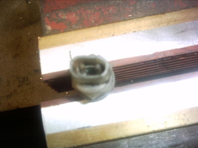
Here's a (bad) picture of the switch. It's blurry but you can see the jumper between the 2 leads.
1971 MGB New Racing Green - Dayton Chrome Wires 72 spoke; General Altimax RT 175/70/14; Pertronix; audiovox cruise control; Moto-Lita 15" wood wheel; Limey relays for headlights, high beams and horn; factory hard top; Clark & Clark seat belt guide clips, upgraded alternator.
1974 Triumph Spitfire
2005 Scion TC - daily driver
2005 Toyota Sienna - my wife's ride, and mine when I need to go to Home Depot.
Attachments:
pressure switch.JPG 26.4 KB
|
|
Apr 19, 2006 08:35 PM
Top Contributor
Joined 26 years ago
25,964 Posts
|
I just went out and looked at the wiring diagram on my wall. My explanation of the switch operation is wrong. The switch has to go to ground through the plunger in order for the light to come on. The reason the cross tie wire is there is to allow the test function of the electrical circiut to work.
Power goes to the switch downstream of the indicator light. If the plunger is off center inside the block, the button on the switch touches the plunger and goes to ground through the block and completes the circiut. The tie wire accross the switch also sends power back to the dash switch, and when the test button is pressed, contacts close and goes to ground through the black wire, and again the light gomes on. Seems like a backwards way to design a system, but what can I say?
Am I making this clear enough?
ground <switch on block T switch on dash > ground
^
power
The "t" represents the connections on the switch where the jumper is
Does this make sense to anyone?
Tried to make a semi drawing with keboard chacters and it did not work. Sure wich ther was a drawing of the circiut I could post
Lord, please give me patience because if you give me strength I will have to ask for bail money, too
Edited 1 time(s). Last edit at 2006-04-19 08:39 PM by Gerry.
Having trouble posting or changing forum settings?
Read the Forum Help (FAQ) or click Contact Support at the bottom of the page.
