
MG Midget Forum
relay wiring
Posted by 1974MGMidget


|
relay wiring
#1
|
|
 |
Topic Creator (OP)
Nov 15, 2018 09:15 AM
Top Contributor
Joined 19 years ago
3,298 Posts
|
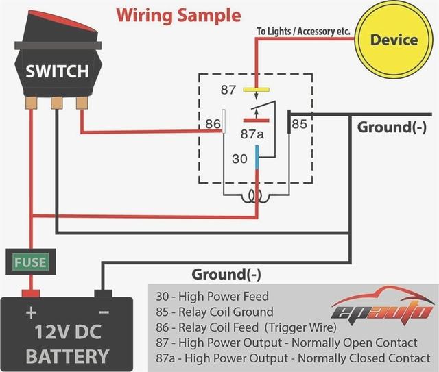
On your typical 12v. relay, you have terminals 85 and 86 which are for the switch, and 87 and 30 for the high power. (wonder where they came up with that naming standard?!). 85 is usually for ground, and 86 for the switch, and 30 is for high power feed and 87 for high power output to light, etc. So, say for the switch, does it matter which of 85 or 86 is ground and switch? And, for the high power side, does it matter which terminal, 30 or 87, the power goes in and which it goes out? I'm guessing it does since they are labeled that way, but it seems like, to a non-EE, that it wouldn't matter which way the DC voltage goes as long as they are on the correct (low or high voltage) circuit.
Attachments:
5-prong-relay-diagram-for-bosch-12v-relay-wiring-diagram-of-bosch-12v-relay-wiring-diagram.jpg 41.1 KB
 Clare, MI, USA
Sign in to contact
|
Nov 15, 2018 10:21 AM
Joined 8 years ago
302 Posts
|
I would use it, and have many times, as it's shown with the 30 being the supply source of power. Simply because that's the coil side of the relay. Does it "really" make any difference, probably not.
In this schematic you have what I would assume is a lighted switch. Normally I only use a single pole switch as a pass through only. In that case there would be no ground wire from the switch. It would only pass through 12v onto the relay coil to pull in the contacts.
This would be the same wiring if you used a temp "switch", not a sender, to say turn on a fan. It would only pass through the 12v to the relay coil.
Just as a bit of added information about cooling fans; they pull about 10A for every 3k cfm. I've ran dual 11" fans before that were rated at 2700 cfm and melted a 40A relay. With relays it is very important to make sure the connections are tight as any looseness will build heat very fast. With the dual fans I ended up running dual 30A relays and my issues were gone.
Sorry for rambling...
Dan Lockwood
O'Fallon MO
|
|
Topic Creator (OP)
Nov 15, 2018 02:31 PM
Top Contributor
Joined 19 years ago
3,298 Posts
|
|
66Sprite
David R
|
Nov 16, 2018 08:29 PM
Top Contributor
Joined 8 years ago
845 Posts
|
When you remove dc power from a coil (ie open the switch) the magnetic field of the coil collapses and as this hapens a voltage spike is created on the switch circuit - this is just physics, read up on induced emf if interested.
A well designed coil for use in a dc application will have a diode wired in parallel with the coil and the purpose of this diode is to prevent the spike travelling thru the system. This diode is shown in the attached diagram, it's the K shaped symbol on the lhs.. If you look at the relay and it has a case you can see thru you may be able to see the diode - it's round cylindrical about 5mm long and 2mm diameter and will have a band on one end.
With this arrangement you should connect the positive to terminal 86. I deliberately haven't used the terms supply or ground ad it depends if your car is positive or negative earth. You want to arrange the positive to 86 which will correspond to the banded end of the diode.
Not all relays have this diode - for switching ac you don't need it as there is no induced emf. I would only use dc relays in my car.
Terminal 87 is connected to the device you are controlling. When the relay is not energised then 30 is connected to terminal 87a, but not all relays will have an 87a terminal, it's just good practice to have the controlled device on 87.
Attachments:
Relay_with_diode_across_coil.jpg 14 KB

|
|
Topic Creator (OP)
Nov 16, 2018 08:55 PM
Top Contributor
Joined 19 years ago
3,298 Posts
|
Having trouble posting or changing forum settings?
Read the Forum Help (FAQ) or click Contact Support at the bottom of the page.
