By now, the benefits of installing a pressurized cooling expansion tank system to the MGA are considered a given.
The problem with left hand drive cars is... Where can we conveniently locate this item under the hood? The location I chose for installing the expansion tank is shown in the photo below:
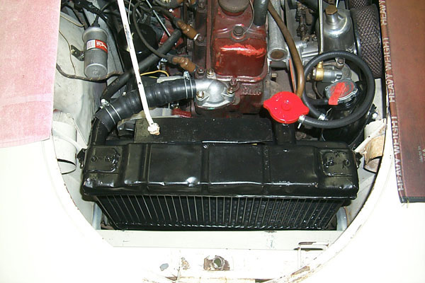
MGA Engine Bay, Expansion Tank Location
Note: The above location is the same as when I modified several MGA cooling systems with twin Lucas electric fans and a pressurized MGB expansion tank with great success in the early 1990s. 20 years later my recent work on a MGA led me to revisit the installation of a pressurized expansion tank system once again...
As seen in the photo above, the original radiator cap as been replaced with a blanking cap. The overflow pipe now directs pressurized coolant to the expansion tank. To achieve this, you can replace the filler neck (or have it replaced at a radiator shop), or work with your original equipment. Let's examine the latter option first.
Using the original MGA filler neck
The blanking cap rubber sealing insert must have a relatively flat surface to seal against. Therefore, I suggest running a fine flat file over the radiator filler neck seating surface. It is also suggested that in order to prevent damage to the rubber seal, you always coat it with silicon lubricant each time you remove and refit the blanking cap.
Never remove the blanking cap without releasing pressure at the expansion tank first! It is also a good idea to paint the cap red, to remind you and anyone else that might be working on the car. The cap in the photo above, while looking slightly pinkish, is actually red.
Your next issue is to remove a section of the original overflow pipe while leaving approximately 1-1/2" protruding from the filler neck.
Now here is the important part. Since the overflow pipe is smooth (non barb style), I strongly recommend fitting two hose clamps. This should be sufficient to prevent the hose from coming off the pipe.
However, instead of this procedure, I recommend removal of the original overflow pipe and filler neck, and replacing with an updated filler neck, which comes complete with a 5/16" barb fitting.
Now let's have a look at mounting the expansion tank to your radiator shroud.
Fabricating the mounts for the expansion tank, 1st Version
The photographs that follow show the initial fabricated bracket for mounting the late MGB expansion tank. This bracket was made from 2 pieces of steel (#10) whose measurements are (A) 1' x 5-1/2" and (B) 3-1/8" x 4-7/8".
Note: This bracket has since been updated and made simpler, please continue reading below.
Bracket (A) was slotted (21/64") to a depth of 3/4" and whose center lines were 4" apart. The center line of the front slot (left) was 5/8" from the edge.
Bracket (B) was simply cut at an angle between the measurements 3-1/8" and 4-7/8".
Bracket (A) was then welded flush on top of (B) as shown in the photographs below.
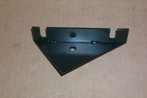
MGA Expansion Tank Bracket, top view
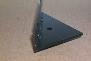
MGA Expansion Tank Bracket, side view
Fabricating the mounts for the expansion tank, 2nd Version
Unfortunately, all our good work was short lived when we decided to install the fan shroud supplied by Moss Motors.
In an attempt to solve interference issues between the aforementioned expansion tank mounting bracket, we modified the fan shroud itself as seen in the top left hand corner of the photo below:
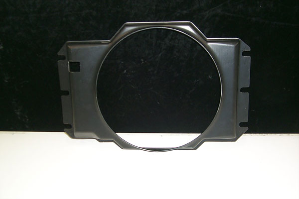
Moss MGA Fan Shroud, modified for expansion tank mounting bracket
Unfortunately, this alone still did not completely solve the issue, so a more simplistic mounting bracket was fabricated.
This allowed us to move the bracket and expansion tank assembly further back away from the fan shroud.
This updated bracket, like the original, is mounted immediately behind the driver's side air induct.
Note: This new mounting bracket can be used with or without the radiator fan shroud.
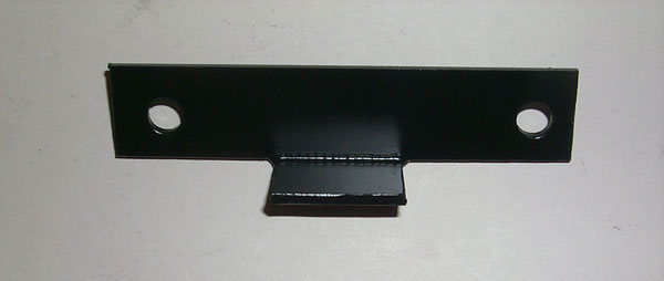
MGA Expansion Tank Bracket, New Design
This bracket is made from 2 pieces of steel (#10) whose measurements are (A) 1" x 4-3/4" and (B) 1' x 1-1/2".
Bracket (A) has two 3/8" holes 4" between centers and equidistant from the center line in width and height.
Bracket (B) is positioned centrally with the 1-1/2" length side running laterally.
Bracket (A) is then welded on top of bracket (B) in such a way that it is flush with the edge of bracket (B). This allows the bracket to seat fully inside the shelving lip.
This bracket is now held in place with a single #12 or #14 (1/4") sheet metal screw. Now, in order to drill the correct location of the pilot hole (#12-5/32" or #14-3/16") a longer drill bit is required. These extended drill bits are used in the aircraft industry and come in 6"and 12" lengths. I suggest the 3/16" x 12" length and then grind it down to the appropriate length for your drill chuck size. The one i used was ground down to 8" in length.
Glue the rubber pad to the back of the expansion tank. When the pad is secure attach the expansion tank and bracket assembly to the mounting bracket with flat washers and nuts only. Tighten nuts, then cut off the excess threads showing on the rear mounting nut only.
Place and slide the expansion tank assembly as far back on the shelving as possible. Now with your long 3/16"" drill bit, make a convenient drill depth indentation on the mounting bracket base.
I found it more convenient to lift out the assembly and continue to drill thru the bracket base with a shorter drill bit of the same size.
Place the assembly back into position and then indent the shelving with the same size (3/16") long drill bit. Once again, remove the assembly and then continue to drill thru the shelving for the #14 sheet metal screw.
Drill a clearance hole in bracket base for #14 sheet metal screw.
If you are only reinstalling the radiator assembly there should be no contact with the expansion tank assembly. Be sure to fit the two radiator packing pieces.
Secure your radiator and install the bottom radiator and water pump hoses first.
Install expansion tank assembly and tighten the sheet metal screw last.
Additional Notes on the Moss radiator shroud
If you are installing the Moss Motors radiator shroud, you may or may not have to modify the shroud as shown previously, or to a lesser degree possibly place a radiator packing piece either side between the shroud and the radiator mounting aperture. If you use the packing pieces they will be easier to install upon final assembly if you slot the mounting holes and slide them into position.
1. With the radiator out and the expansion tank assembly removed, temporarily place the fan shroud into position and slide as far to the passengers side as possible without touching the fan blade assembly.
2. Refit the expansion tank assembly. If there is interference, this can probably be rectified by fitting the aforementioned radiator packing pieces. If not, you will then have to modify the fan shroud.
3. If fan shroud modification is required, mark the area where interference is occurring. Remove fan shroud for modification. In making this cut out, I found it easier to drill a series of 1/4" holes then finish the job with a hacksaw and a file. If you do the job correctly, it will look neat and tidy as shown above.
I was able to accomplish the modification with no need to use the additional packing piece method. However, having said that, there is always exceptions when it comes to an individuals skill level.
Along with the fan shroud installation instructions from Moss Motors, proceed to fit the radiator, fan shroud, hoses and expansion tank assembly as outlined earlier.
Finishing Touches
The expansion tank will now carry a short style pressurized radiator cap of your choice. Modern day vehicles run much higher cooling system pressures. The later MGB, fitted with this expansion tank system, ran with a 15 lbs cap.
I prefer the "stant type" with the pressure relief lever. However, you are limited to your choices if you use this style of cap. I installed a cap rated for 13 lbs.
For the radiator filler neck barb to the expansion tank barb, you will need approximately 18" of 5/16" ID hose (cut to suit). I actually used 5/16" ID high pressure fuel hose.
For the expansion tank overflow you can use regular 5/16" ID vacuum hose. You will need around 18". This can then be directed downwards to empty underneath the car if the system exceeds the max pressure of your radiator cap.
The radiator shop positioned the new filler neck with the barb facing the same direction as the original overflow pipe. I think the routing looks clean, and more importantly, leaves the hose kink free.
Fill the cooling system with 50/50 coolant to distilled water, which includes filling the expansion two thirds full. Lubricate the rubber seal on the blanking cap. Failure to do so may result in damage to the seal the next time you try and remove the cap.
If in the unlikely event that the blanking cap leaks, buy another blanking cap and take out the rubber seal and double up on the seals.
Moss Motors items:
- Expansion tank (459-690)
- Expansion tank bracket (459-691)
- Rubber pad (459-692)
- Radiator filler blanking cap (780-126)
Misc items:
- Stant 13# radiator cap 10329. (NAPA 703-1700)
- 2x hose clamps (miniature) #4
- 5/16" ID hose (pressure & vacuum) - 18" of each
- 2x #14 sheet metal screws
- 3/16" extended drill bit (12")


When the car cools down the vaccum caused in the rad pulls water back up from the catch tank. This is the way most modern cars work and I've been doing it on my B for years...
For the MGA there is no benefit to using higher pressure in the cooling system. 50/50 coolant and 7-psi will have boiling point of at least 245dF, way past end of scale on the temperature gauge. Going to 13-psi moves the boiling point up to 265dF. Such high operating temperatures will cause problems with boiling fuel in SU carburetors (sometimes even at 220dF in standing conditions in hot weather). If your MGA ever runs past 230dF (with a fan shroud), there is something wrong with the radiator.
Placing the expansion tank in the position shown obstructs service access for carburetor adjustment and the lower coolant hoses. How often are you willing to dismount the expansion tank for other service access?
Thanks for your input. There is a fundamental difference in the overflow catchment tank and the pressurized expansion tank recovery systems.
In the latter the cooling pressure is controlled by the pressure cap on the expansion tank and not the radiator. This essentially then becomes a closed system.
In the event that excessive running temperatures are reached (near or at boiling point) there is less likelyhood of the coolant overfilling and overflowing from the overflow catchment tank when the vehicle is parked.
I have carried this modification on MGB's over the years and sold many of my expansion tank kits with great success. Installing your current system may also well work effectively on the MGB. However, the challenge with the LHD MGA is the location of said expansion tank components.
Thanks Doug (wwwmgbmga.com)
Thank you for input.
This pressurized coolant expansion tank system is designed to improve the integrity of the cooling system. It is a closed system that is designed to prevent coolant being being dumped unceromoniously on the ground especially when the vehicle is parked. It does not control the running temperature of the engine.
On the subject of the radiator joints not standing 13lb pressure, I would imagine all OEM radiators at this stage of their lives have been repaired or replaced. I believe radiator shops do pressure test their radiators after repair and would suspect the would be using a test pressure higher than the 7lb that you state.
If you were to do more research on why OEM radiators fail at the joints you will find that their is evidence that the radiator itself becomes a stressed member especially when the vehicle is driven hard.
In the event that your MGA begins to boil there is less chance of the 13lb cap ejecting coolant onto the floor than the 7lb cap when the car i
The pressurized remote tank is simply an increased volume for the radiator top tank. It keeps the radiator top tank full of liquid, but otherwise it still has to breath the same as the one originally on top of the radiator. The only way it could be a closed system would be if the remote tank was large enough volume to accommodate all of the thermal expansion of the fluid by compressing air inside the tank, and never venting air out or in through the pressure cap.
First and foremost you condemmed this kit from the very start, yet you have not even attempted to install it.
You keep on about cooling temperatures, yet no where in my article did I ever mention that increasing the poundage on the pressure cap would be beneficial to controlling coolant temperatures.
Now your talking about thermal expansion, pressurized cycling on hoses and the radiator as well as the expansion tank not being a truly closed systemn.
You seem intent on trying any angle to find fault with what has proven to be a successful installation.
Please I have more to do with my time, as I am sure that you do.
Want to leave a comment or ask the owner a question?
Sign in or register a new account — it's free