Many people have reported problems with ill fitting Midget front wheel bearings and short life spans, and some incorrect information has been floating around about what works / does not work, and whether the spacer can be eliminated, and so on. I wrote this to try and gather all of the information together into one place on this subject, including the input from a lot of people who have worked on this over the past year or so.
This article is written in several parts:
Intro, and Figure 1, as a quick means for anyone to grasp the key things they need to know when servicing / replacing the MG Midget Front Wheel Bearings.
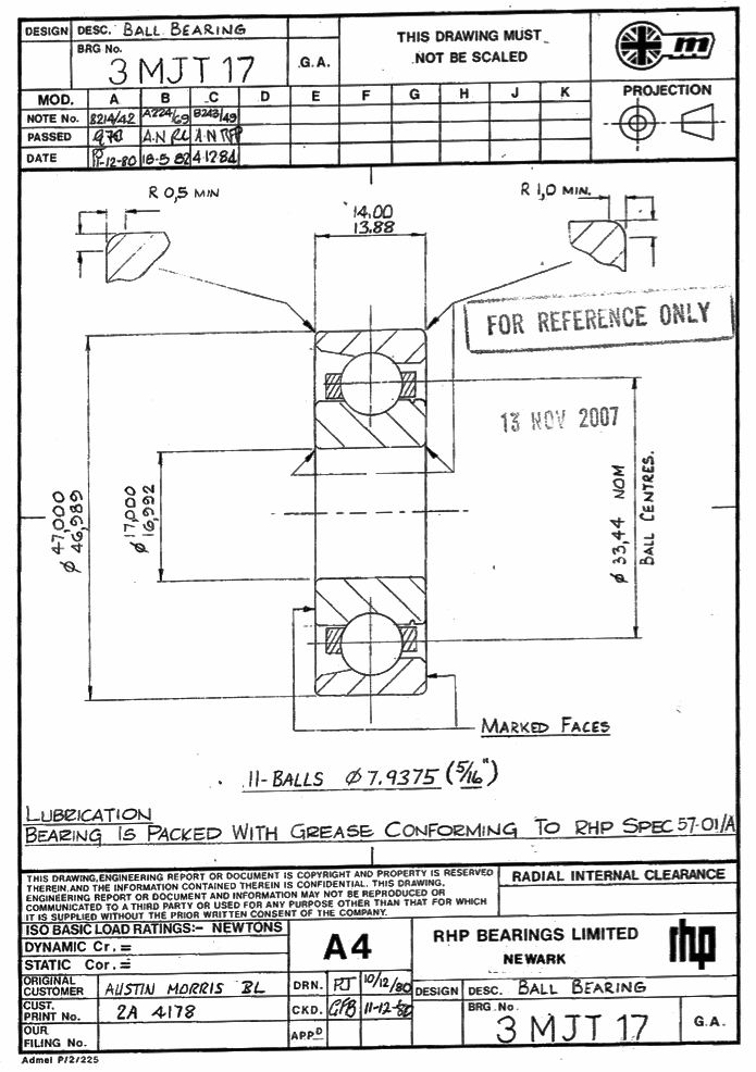
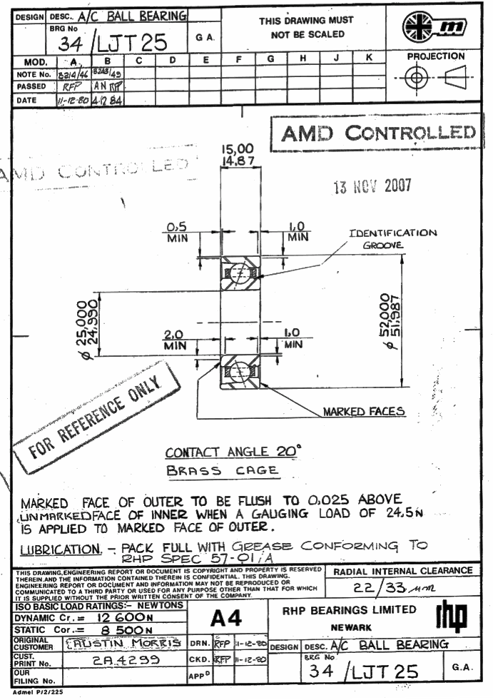
Attachments 1, 2, 3 are more in-depth, to answer any questions about the "why", and attachments 4 and 5 are the original drawings from RHP (provided by Robert Welch, MGCC member and knowledgable Spridget owner for over 48 years)
Introduction
The whole MG Midget front suspension is "unusual", the lower pivot uses a threaded pin, and the kingpin assembly requires frequent, careful greasing to maximize its relatively short life.
The front wheel bearing system is also unusual (refer to Figure 1). It uses ball bearings, like modern cars use, but they are assembled in a way that depends on several components to control their proper fit. They are very difficult to remove from the hub without separating them, which damages the balls and races if that happens. As a result of this design, all of the parts must be checked carefully BEFORE assembly.
There is no reason why the front wheel bearings on a Midget shouldn't last the life of the car, as they use a very liberal design (the pitch between the bearing centers is >1.5", where modern cars weighing twice as much have half of that), but they often fail early due to improper fitting.
This subject was not much discussed in the manuals because the OEM bearings were still readily available, and when using those it is simply a "fit and forget" design. Unfortunately, those OE bearings have become scarce, and expensive, so suppliers have tried substituting "equivalent" bearings that cause fitting issues; wheels that wobble, brake rotors rub on calipers, or bearings that fail quickly.
The purpose of this article is to provide a guide for folks replacing their front wheel bearings so that they all can experience the maximum life out of these parts.
Original bearing part numbers, with these you should have no trouble *. (refer to RHP drawings attached)
Inner bearing:
34/LJT 25 made by "RHP UK" (original Austin/Morris part number: 2A 4299) 39/LJT 25 is equivalent, with a resin cage. Both of these have the all important 2 ~ 3mm radius to clear the stub axle fillet radius at its base.
Outer bearing:
3 MJT 17 made by "RHP UK" (original Austin/Morris part number: 2A 4178) 11/MJT 17 is equivalent, with a resin cage.
* Two key points about the bearings listed above: - they are "face adjusted", which means that their inner and outer races are machined to be < 0.001" from each other, crucial for preventing too-loose / too-tight fit in the hub. - the inner bearing has a ≥ 2mm radius so that it won't interfere with the stub axle fillet radius when installed.
Two confirmed sources for the original bearings are:
- Ransome and Marles: http://www.ransomeandmarles.co.uk/

- Bearings Impex Queen Street Crewe Cheshire CW1 4AQ Tel.01270 585211
What about cheaper bearings from "the usual sources"?
There are cheaper bearings around. Moss, and the usual suspects, sell "equivalent" bearings *. But to avoid trouble, or when in doubt, fit the original bearings listed above, instead.
* When ordering bearings, most suppliers use the generic part numbers listed below (note that these are not the original Austin/Morris part numbers):
- GHB 129 (inner) — GHB 128 (outer) — GHK 1294 (kit, including seal and split pin)
But when ordering these numbers, what bearings are actually supplied? - NSK: 7303BEAT85SUN / 7205BEAT85SUN
SKF: 7303BECBP / 7205BECBP
These NSK and SKF parts are supposed to be face adjusted, but if you try to use them, make sure that they also have the needed ≥ 2mm radius to clear the stub axle.
What about tapered bearings?
As noted later, you will see that tapered bearings can be used. IF they have the necessary radius to clear the base of the stub axle, AND the spacer is used between the inner and outer bearing, and if the whole assembly is then properly shimmed to keep the 0.002 ~ 0.004" play the bearings require after the hub nut is torqued. The advantage of tapered in this case is that they can easily be removed from their outer races for shimming of the assembly (and that is why the larger, heavier, more recently designed MGB used them!).
The instructions for how to shim them are based on the MGB hub, which is almost the same as the Midget's, except for the fact that it is designed to be shimmed, and the Midget is not (refer to attachment #2).
What is the spacer for?
The spacer is required for max stub axle strength and fatigue life (refer to attachment #1).
Why replace the wheel bearings?
- Wire wheel hub replacement (because worn splines require new hubs). You can try to remove your good bearings from your old, worn hubs, but if they come apart, they've been damaged and their life expectancy is shortened (no one can say by how much, even the bearing makers admit that, they just know that some damage has been done by the force of the separation, peening flat spots on the balls and/or into the races).
- Play in the bearings (as opposed to play in the kingpin / A-pan assembly from wear in those parts), identify which is the cause by a "wheel wiggle test" with and without the brakes applied (if it goes away with the brakes, it is worn bearings, if it does not go away, it is worn suspension joints).
Note that these bearings are not designed to be periodically removed and re-greased the way American cars were in the ‘60s and ‘70s. According to John Twist at University Motors, the most common issue he finds in MG wheel bearings is a lacking of grease at the outer bearing, which is easily remedied by adding some more. He said that in all of his years of MG service, he's "never seen an inner bearing that did not have enough grease".
So, for instance, when removing the hub to replace the brake rotor, if there is no sign of worn bearings before starting, just keep everything real clean, check the outer bearing has enough grease, and put the hub back without disturbing the bearings.
How to remove?
Ideally, drift the outer bearing out by moving the spacer over so that it presses on the outer race (very difficult to do), and then removing the inner bearing is simply a matter of pressing on its outer race with a drift. Or, "pop" the bearings so that the balls fall out, and then decide whether to risk re-using them, or buy new ones instead.
How to confirm the parts are OK before re-assembly?
- If the bearings are not confirmed to be "face adjusted", you can inspect them like this: - load the outer race 5.5lbs axially. - measure the levelness of the inner race x outer race (thrust face of outer race must be 0.000 ~ 0.001" above the inner race). Reference RHB drawings (attachments #4 & 5).
- Measure the fillet radius at the base of your stub axle (typically 1.5 ~ 2mm), and make sure the radius on the inside of the inner race of the inner bearing is ≥ 2mm. It can be very difficult to measure these accurately without a radius gage set. Alternatively, you can trial-fit the inner bearing to the stub axle, by itself. Confirm that NO gap exists between the bearing and the load face of the stub axle. This confirms that the radius clears the fillet.
- Some of the new wire wheel hubs being sold have an unnecessary fillet radius where the OUTER bearing belongs (reference attachment #3). Confirm your new hubs don't have this flaw. I got bad parts this year from both Victoria British (US) and from Leacy (UK), but got good ones, finally, from Moss (US). Other than this radius, all three pairs looked identical to each other, including the manufacturing sticker on the flange. VB and Leacy refunded my money, but showed no interest in trouble shooting the root cause of the bad parts, and will probably just sell them to someone else...
- Confirm that the spacer is exactly 1.500". The MG spacers were face ground originally to be spot on, but some DPO may have cut / sanded them down on your car to fit non-standard bearings in the past. If your spacer is too short, your new bearings will be crushed by the nut torque and have a short life.
How to assemble everything properly?
- Grease the outer bearing and press it into the hub (see Figure 1 for orientation).
– use a ⌀ 1 3⁄4" drift.
– do NOT press on the inner race (doing this will damage the balls/races) - Confirm it is FULLY driven home by measuring the distance from the inner race to the "shelf" that the inner bearing seats against. This should be 1.496" ~ 1.498". If you get more than 1.500", your bearings will be crushed by the hub nut torque and have a short life.
- Insert the spacer
– apply some grease around the outside of the spacer, between it and the hub. - Grease the inner bearing and press it into the hub (see Figure 1 for orientation).
– use a ⌀ 1 15/16" drift.
– do NOT press on the inner race (doing this will damage the balls/races) - Lubricate the seal lip and press it into the hub (see Figure 1 for orientation). – use a ⌀ 2" drift. – shop manual calls for engine oil on the lip of the seal.
- DO NOT pack the area between the seal and inner bearing with grease because when the bearings heat up the grease will expand and if this space is already full the grease will be pumped out past the seal and it will fail.
- Check the stub axle for nicks / burrs where the bearings go, and where the seal runs.
– smooth surfaces will help assure the bearings come off easy next time, and avoid seal wear. - Assemble the brake rotor to the hub
- Assemble the hub assembly to the stub axle
– don't damage the seal by catching it on any sharp edges. - Torque the hub nut (15/16" socket) to 46 ft-lb, or until the next castellated nut lines up with the hole (up to 70 ft-lb).
- Install the split pin and the grease cap
– do not pack the grease cap full of grease (for the same reason as #6, above).
Figure 1

MG Midget & Healey Sprite front wheel bearing hub, bearings, races cross section diagram
Attachment 1 - Stub Axle Modulus Study
Attachment 2 - MG Midget vs MGB Hub Bearings
The MGB hub is structurally the same setup as a Midget, but there are three key differences:
- The MGB has a spacer inboard of the inner bearing. This spacer does two things, it deals with the large fillet radius at the base of the stub axle, and it provides the sealing surface.
A midget has no spacer at the base, so it is very important that whatever bearing is used for the inner bearing HAS the proper radius for it to go all of the way on. This necessary radius is 2mm, and most modern bearings only have a 1mm radius, meaning that they will not fit properly. The difficult thing about this point is that it is not something you can "see", unless you trial fit your bearing onto the stub axle before you press the bearing into the hub. If you do this check, you can confirm that it seats fully against the face of the stub axle with 0.000" gap. Any gap here that is not accounted for will move your brake rotor outboard (may interfere with the caliper, in severe cases), can cause your lip seal to "fall off" of its sealing surface (rendering it useless), and, most importantly, will create a stress riser that could possibly cause your stub axle to experience a fatigue failure. Shimming this area will prevent the stress riser, but does leave the first two concerns. - The MGB uses tapered roller bearings, the Midget uses ball bearings (20 deg angular contact ball bearings).
Tapered roller bearings can be installed and then removed easily. The freeplay of the whole assembly can be measured with the nut torqued, then they can be removed to adjust the shim thickness behind the outer bearing. Very accurate, and very easy to work with. Ball bearings, on the other hand, can not be removed from the hub once they have been installed. Removing them is very difficult without ruining them (if, when pressing them out, the inner race comes free of the outer race, the balls come out and damage is done to the balls and the races which may lead to premature failure). It is maybe possible to re-use them, but it is risky and the manufacturer (and the Machinery's Handbook) recommend against doing it. - The MGB hub assembly is shimmed for the proper bearing freeplay, the Midget is not designed to be shimmed.
The Midget hub was a "fit and forget" design, "good enough for a low weight, low powered, low cost car". Once the bearings are pressed into the hub, it is unlikely that you will get them out again without separating them. Therefore, the parts used in the Midget hub must be confirmed to be the right shape BEFORE you put them together. If they are not right, they won't last. - This "fit and forget" design is the 3rd difference to the MGB hub.
The MGB is meant to be shimmed until it is correct. But, for the Midget, It is very important to confirm the bearing shape, the hub shape, and the middle spacer shape are all correct, before assembly, in order for your new bearings to last. The OEM bearings from RHP were face adjusted to within 0.001", this means that the inner and outer races are the same thickness. If your bearings are not RHP (or Ransome and Marles, their successor), then you must confirm what the face difference is and adjust for that during initial assembly. The problem with doing this is that the bearing must be gauge loaded to 5.5lbs for measuring. Probably easier, then, to use the RHP OEM bearings, 3MJT17 and 34LJT25. MGB shimming method.
Notes:
- Both the B and the Midget have a spacer between the two bearings. This is very important structurally, because it creates a "pipe" to carry the loads and has a much larger diameter than the stub axle alone (providing 1.7 times the section modulus). The shape of this "pipe" also smooths out the section changes along the length of the stub axle, helping to minimize the stress riser at its base.
- When the hub nut is torqued, that "pipe" is carrying the load. If the spacer is too short (say, a previous owner sanded it down to take up worn bearing play), the new bearings will then be over tightened, leading to their premature failure.
- If the new inner bearing has too small a radius it will hang up on the stub axle radius and lead to the issues mentioned in 1) above (previous page).
- If the new bearings are not face adjusted to 0.001", the stack up height of the assembly may be too loose, or too tight, leading to excess play, or excess load, both can lead to premature bearing failure.
- The distance between the two outer races is 1.496~1.498", machined into the OE hub. The length of the spacer is 1.500". These two dimensions control the 0.002 ~ 0.004" free play of the bearings.
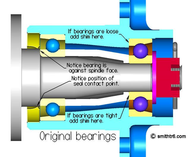
Adding shims to achive proper bearing play, Midget & Sprite
Here's an interesting thing: there should be no reason why tapered roller bearings could not be used in the Midget hub. If the inner bearing that is used has the necessary 2mm radius to clear the base of the stub axle, and if the whole assembly is shimmed properly, using the spacer between the two bearings (following the MGB shimming procedure). The MGB shimming procedure is shown on the next page.
How to shim MGB bearings (with red circles showing correct seal orientation):
With excerpts from a great tutorial posted by Paul Hunt here: http://www.mgb-stuff.org.uk/suspensiontext.htm#endfloat
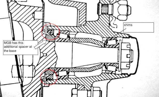
MGB bearing cross section digram, shim locations
The Factory Manual is quite clear on the need for a particular end-float i.e. 'free play' to be present with the type of taper roller bearings used in the MGB. Anyone who tells you to apply a pre-load of X lb ft (i.e. the opposite of end-float) or whatever is wrong. That may be correct for other automotive applications, but not for the MGB. Some say that you don't need shims in the front hubs, some even say you don't even need the spacer. They are mistaken, you do need them because the act of clamping the inner races, shims and spacer between the hub nut and the base of the axle spindle significantly increases its strength.
Compare the MGB with the Midget front hub:
Note that the bearings are positioned the same way, though these are ball bearings, their races are loaded diagonally, with the outer races installed towards each other, just like the B:
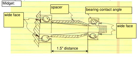
Detailed MGB shimming instructions.
The MGB shims come in three sizes: 0.003, 0.005 and 0.010. Ideally, a dial gauge* is used for estimating end- float and confirming it. Roughly 0.060" is a typical starting point for shimming an MGB hub assembly.
- When replacing bearings assemble everything lightly oiled first (i.e. without grease) as it keeps things cleaner and is easier to set the end-float.
- The order of parts on the axle is: oil seal collar - inner race of inner bearing - spacer - shims - inner race of outer bearing - bearing retaining washer - nut.
- The first time you assemble the parts onto the hub leave out the shims and tighten the nut until the bearings drag slightly (not bind) while rotating, to snug the bearings to each other in the hub.
- Now fit the shims between the spacer and the outer bearing. The objective is to add and subtract shims until you get an end-float of .002 to .004.
- Keep juggling shims until you get two combinations that are ideally only .001 apart where the thinner combination gives no end-float and the thicker gives perceptible end-float i.e. -0.001 to +0.001. Use the lower combination and then add another .003 shim. This should give you the required .002 to .004.
- When you have determined the correct shims remove the races and inject or press grease in one side only! Keep going till the grease comes out the other side, and leave a bulge of grease on both sides. Don't be tempted to save time by greasing from both sides you will trap air in the middle of the bearing and possibly cause premature failure.
- Lube the oil seal that goes at the base of the axle shaft with motor oil / light grease.
- Reassemble everything, tighten the nut to 40 lb. ft., then tighten further until a hole in the shaft lines up with a slot in the nut. This should occur well before the maximum torque of 70 lb. ft. is reached.
(Interesting: note the MGB torque starts at 40, where the Midget started at 46)
* This Huey tip Posted by Mike DeLorey, 8/26/2010, MG Experience BBS, MGB section:
"If you can't use a dial indicator, you can go by feel. If the hub spins free, and you can feel axial play but not see the movement you are there. If you can feel and see movement you have .005" or greater axial play. .005" is about where you can start to actually see movement. For any of the old timers out there that were former Army aviation and had to shim the sync elevators on a Huey or Cobra that's how we checked the axial play."
Attachment 3 - Hub Radius Issue
Watch out! Some replacement wire wheel hubs are machined incorrectly and should not be used.
Here is how to spot a bad one:
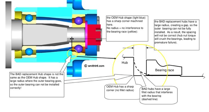
Incorrectly machined replacement hub
Original Bearing Drawings from RHP


Question, when reassembling bearings, spacer and shims in hub, tightening to prescribed
torque, wheel doesn't turn very easily. Is this the result of too many shims? Should I
remove some shims so that hub turns?? Shouldn't the hub turn easily?
Mark
Adding shims will make it looser, removing them will make it tighter.
The goal is to achieve an end float (looseness) of 0.002 ~ 0.004" when the nut is torqued.
Note that the Midget assembly does not use shims, its end float is provided by the 1.5"
machined spacer and using bearings that are the correct thickness.
So, this comment about shims only applies if an "MGB" approach is being substituted (using
unique bearings and a unique spacer on a Midget).
Norm
I have been trying to reassemble by MGA front wheel bearings onto the spindle for my 1960 MGA, are these the same as the Midget? Looks very similar to your drawings. I am having difficulty getting the outer bearing to fit onto the spindle. I measured both and there should be 0.002" clearance. Why am I having so much difficulty getting these to fit. Should I use a drift? What size drift for the inner and outer wheel bearings?
Here is his page on the MGA front wheel bearings: http://mgaguru.com/mgtech/suspensn/fs112.htm
that one and also, the 4 articles that follow that one.
The bearings need to be pressed into the hub, with a suitably sized drift (one which will only push on the outer race and never load the bearings themselves while doing so).
On the other hand, the completed hub assembly should then slip on / off the spindle without needing pullers/ drifts.
From your description, since your measurements tell you that there should be clearance, then I suspect your trouble is a burr on the spindle which is not detected by your measurement, and
that is interfering, causing the bind. Take an emory cloth and loop it around your spindle and see if a few minutes with that will clear up your trouble.
Hope this helps,
Norm
The bearings fit into the hub fine by just tapping slightly on the outer race. Its when I try to slip the completed hub assembly onto the spindle that I have the difficulty. I seem to have difficulty even separately from this just slipping the outer bearing itself onto the spindle (as a test) I cannot get it to slip on. I have tried a couple different new bearings as well as the original. So I think your idea of smoothing out the spindle, making sure there are no burrs (etc) may prove helpful. My understanding is that the bearings (completed hub with bearings installed) should slip onto the hub without the need to hammer or draw it on. I e-mailed Barney Gaylord and I believe he said they should slip on. So I must have something preventing this. A mechanic I know suggested I freeze the spindle to shrink it or heat the bearing (which I can't really do because it is in the hub and the heat may destroy or damage the inner seal.) I will let you know how this goes once I have a chance to work
Want to leave a comment or ask the owner a question?
Sign in or register a new account — it's free