
MGB & GT Forum
UPDATED Question: Tach, where none went before...
Posted by KRCaddis


|
UPDATED Question: Tach, where none went before...
#1
|
|

KRCaddis
Gene Johnson
|
Topic Creator (OP)
Apr 17, 2024 06:04 PM
Joined 11 years ago
139 Posts
|
Updating from home (yesterday I was waiting a the bus stop for my granddaughter)"
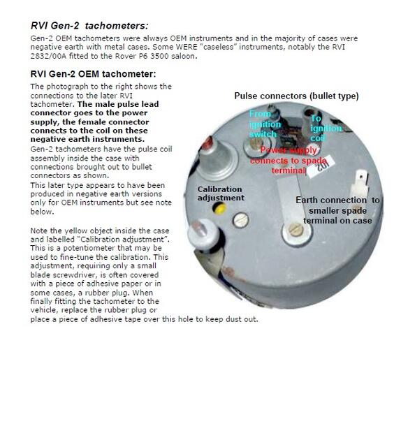
Attached is the image and text about the specific type of RVI Tach that I'm installing. You will note that there's a male and female bullet connectors as well as a male spade for +12v, and a narrow spade for ground.
UPDATE
After thinking "out loud", my brain was telling me that "in series" means the signal feeds from the output (pulse) side of the coil, into one bullet connector then out the other (though the tach), then to the dizzy in a rather lengthy loop for that low tension/high voltage wire.
I hope that the annotated photo from the "Gentleman's Guide ..." better clarifies my post question from yesterday. I routed a white/black wire to make that in-series connection but I'll have to wait until I start the engine to test it. I do welcome clarifications from others who interpret the photo and text differently.
I'd tried other salvaged Smiths tachs, probably different versions, in the past using the one wire parallel to that LT coil wire but I had only brief success and always ultimately failures getting any bounce or briefly any reading. This new tach was sold as NOS, so it should be functional. I get zero resistance between the bullet connectors. indicating continuity.
https://www.triumphclub.co.nz/wp-content/gallery/pdfs/Smiths.pdf
I'm installing a MG Midget/MGB tach in my Minor, negative ground (earth) and have a question about the pulse feed wiring
It's a second type of RVI type that appears to have two points of connection, bullet type, for the pulse from the coil to distributor . "The Gentleman's Guide to Tachometers" refers to those both for the pulse point wires, IN SERIES. Am I correct in understanding that the white/black tracer wire t runs from the coil through the tach, and back to the coil? There's a male and female connector on the tach; is the female one FROM the coil, Male TO the dizzy? Hoping this is coherent as I'm on my phone typing 2 mm text with 2/3 visible and if I rotate, the screen keyboard covers half of the text. Swiping,,I may be wiping out parts... No photos or links . The Guide is from the Triumph club of New Zealand, I think...
Edited 1 time(s). Last edit at 2024-04-18 05:06 PM by KRCaddis.
Attachments:
Tach Back.jpg 55.5 KB
|
Not-Anumber
Chris S
|
Apr 18, 2024 04:14 AM
Top Contributor
Joined 10 years ago
444 Posts
|
According to the wiring diagrams for MGBs between 1964 and 1967 yes the tachometer is wired in series with the ignition coil. These tachometers had a + voltage in (switched by the ignition switch) then an output to the + side of the ignition coil (both these wires were white, in and out) Then just a ground connection.
From 1968 there was an additional green wire to the tachometer from the instrument voltage stabiliser in addition to the above.
But then from 1973 onwards it changed again. This time the tachometer still had a feed from the gauge voltage stabiliser but there was no connection at all to the + side of the coil on a white wire. Instead it had a parallel connection from the - side of the coil (tapped into the wire between the = coil and the distributor/ points) on a White/black striped wire. . Then a ground wire. Completely different.setup.
 Geelong Victoria, Australia
Sign in to contact
|
Apr 18, 2024 05:45 AM
Top Contributor
Joined 13 years ago
15,861 Posts
|
OK Gene,
The normal connection for that tacho, which I think is the later version, having a wire come out with two connectors.
The male connector goes to the ignition switch, whilst the female goes to the +ve terminal on the coil. This provides the power, 12V, to the coil. As the points open and close there a current pulses, about 4A, in the loop, inside the tach. This creates the triggering for the electronics. This tacho needs a constant 12V to drive the electronics and the coil feed. I've successfully used one white wire from the ign switch to both the power terminal, a 1/4" spade, and the current sense male connector.
Herb
Questions about prostate cancer? Click here to join the discussion
Edited 1 time(s). Last edit at 2024-04-18 05:45 AM by ozieagle.
Forums 
Having trouble posting or changing forum settings?
Read the Forum Help (FAQ) or contact the webmaster
