
Ford EDIS (Electronic Distributorless Ignition System) Crank Fired Ignition Conversion on a 1965 MGB
06/14/2010 by Marty Schmitz-Hertzberg
I was tired of bad distributors, and questionable advance curves, even though there are some excellent rebuilt units around.... I also was also curious! I stumbled across an electronic 'box' from Autosport Labs, designed and marketed by Brent Picasso called "Megajolt Lite".
Others have done this conversion before, so I wasn't breaking new and uncharted territory!
After reading his web site, and perusing the users bulletin board I was hooked... there were reports of fast starting, and smooth idle on A and B series engines, and more responsive throttle.. a veritable panacea of goodness! I also like tinkering so time to make it happen.
The Megajolt (MJ) system is designed to work with components from Ford products from 1990 to 2000 (roughly). The Ford system is called EDIS, and has a control unit, a high energy 'electronic' coil , a 36 tooth wheel attached to the crankshaft and a sensor which reads the pulse from the wheel. The system is the same on 4 6 and 8 cylinder cars, just more coils. There are lots of articles around on EDIS, even on Wikipedia, so I won't go into any more details.
The system requires crank position and either throttle position sensor or a manifold pressure sensor. I chose MAP as I believe it is more flexible and tells truer state, rather than where the throttle butterflies are physically. On modern FI system both these inputs are used.
The Megajolt unit comes either assembled or in kit form, I chose to buy the assembled unit, with the MAP sensor built into the unit.
I now needed to source the rest of the bits. Ebay, Ford, Kijiji and triggerwheels.com soon provided all the rests of the bits. I could have gone to the scrap yard but I never seem to find the time.
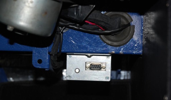
Megajolt unit installed, passenger side footwell. I added a blue LED to tell me if the unit has power
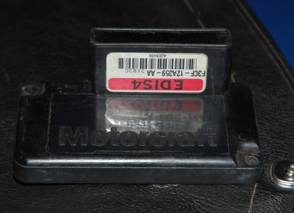
Ford Motocraft EDIS4 Control unit
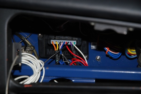
Ford EDIS control unit mounted behind the MGB glovebox
Trigger Wheel and Sensor
The biggest problem was: how do I mount the trigger wheel? On a chrome bumper MGB, there isn't a lot of clearance between the crank pulley and the steering rack. I did see one setup where they had machined holes in the back of the flywheel, to 'make' a pulley! I also saw A series pulleys with the teeth milled into them.
I bought a trigger wheel from triggerwheels.com in England. They had a trigger wheel setup that included a spacer to mount the wheel on the solid part of the pulley, and it spaced the pulley out in front so it didn't interfere with the rubber mounted part of the pulley.
The wheel was 5.75 inches which is almost exactly the diameter of the MGB pulley. I machined spacer so the trigger wheel was only a few thou off the front of the pulley, and I then machined the outside diameter of the pulley smaller so the sensor would provide a good signal. I know there is a lot of theory about the exact size and weight of the pulley to balance harmonics in the engine, but I machined it anyway. The next one I do will use a 6 inch wheel.
I made a solid bracket to hold the sensor @24 thou from the sensor wheel. I also needed a longer pulley bolt, which is a 'A and B series only' bolt so I had the machine shop make one. I drilled some locating holes on the crank pulley , set the wheel in the right spot pinned it, and bolted it up. There is about ¼ inch clearance to the steering rack.
I was concerned that the engine may move slightly forward under heavy braking, so I ensured that the plates that come bolted to the motor mount had very tight clearance, so if the engine moves the plates will stop it.
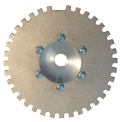
Trigger Wheel from Triggerwheels.com
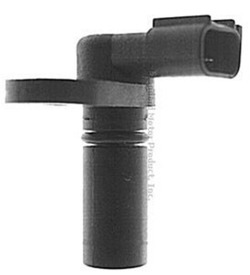
2000 Ford Taurus Crank Sensor. Just about any Ford sensor will work. I chose this one because of the way I planned to mount it.
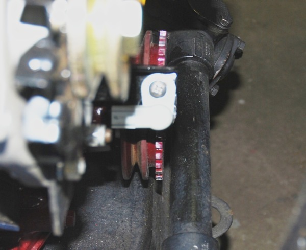
Trigger wheel to MGB steering rack clearance
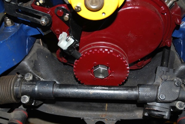
Trigger wheel and Taurus crank sensor installed on MGB engine, front view
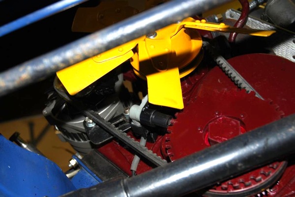
Trigger wheel installed on MGB engine crankshaft pulley, bottom view
Ignition Coil
The EDIS coil is quite a beefy unit, and has the plug wires directly into it.
I removed the guts, and cut into an old Lucas distributor until I could 'bolt' the coil to it. At first glance it appears to be a regular distributor.
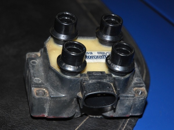
Stock Ford Motocraft EDIS Coil
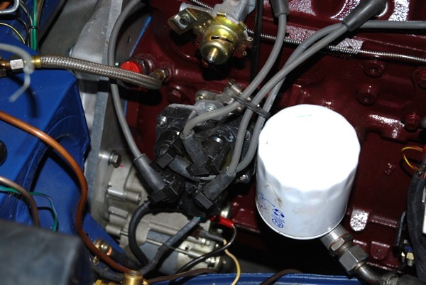
Ford coil, mounted on stock looking MGB distributor
Vacuum pipe
I connected the vacuum pipe to the cross tube on the SU manifold. It is connected to a @ 40cc reservoir screwed to the bulkhead (where the original OD switch was), and is made from 2 PVC end caps for capping pipes for a built in vacuum cleaner. It then goes into the Megajolt unit. This reservoir is to smooth out the vacuum signal 'pulses' to the Megajolt unit so it doesn't 'wander' the timing at idle. This behaviour is worse with a 5 port head.
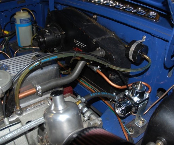
Vacuum connection on SU manifold and Megajolt vacuum reservoir
Wiring
I made a wiring loom, paying careful attention to the cable from the sensor to the EDIS unit and from the EDIS unit to the Megajolt unit. This signal must not have any interference, so I used a 2 wire fully shielded cable. The whole system is powered from PIN 2 (with a 15 A inline fuse) on the ignition switch, just like the original distr/coil setup power source.
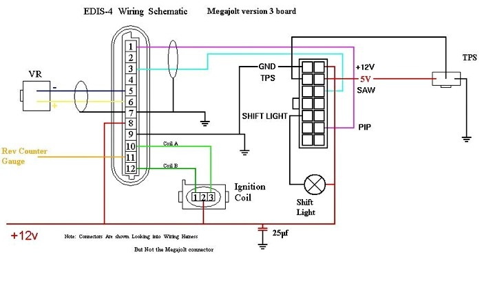
EDIS-4 Megajolt V3 MGB Wiring Diagram
The tachometer is driven from a port on the Megajolt or the EDIS unit. I am using a tachometer which looks like an early MGB tach, but it has the electronics from a late model MGB tachometer installed in it. If there is a problem with these signals (they are weak), the tachometer can also be driven directly from the coil signal with a pair of diodes.
Setting it up and getting the car running
The first test I did was to fire the car up without the Megajolt unit attached. One of the features of the EDIS system is that is will run a car at 10 degrees advance with no external control... it is a 'limp home mode'.
I put my timing light on to check that it was indeed 10 degrees, and that confirmed my installation/position of the trigger wheel and sensor.
Next was to connect the Megajolt unit and download the map to the unit (I got the map from the how it's done section on the Megajolt site).
Immediately I could hear the difference, and I could see the MAP readings!!
Now to take the car for a drive...
Impressions
The car starts from dead cold in a few turns - it took considerably more with the distributor. It then drops into a stable idle. When it's hot, it starts immediately. The car seems to rev more freely and pulls much harder through the gears with no flat spots. It always has a 'hard' exhaust note.
I am getting used to the car, and will start playing with the map, but right now there doesn't seem to be a need.
Cost
All done and told I spent about $450, and about 30 hours of my time learning , making and remaking parts, wires and making mistakes. The next one I could do in few hours. Autosport Labs now has a new version of the Megajolt unit, with more programmable features, and a fancy case!
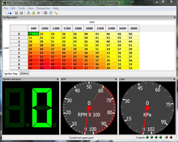
Megajolt Lite configuration program showing the map I am running in my 1965 MGB

")


You say that ignition is run of number 2, yet there is no wiring showing there on your diagram.
I am trying to link up an MJ to mine and have everything done bar the connecting up to the key switch, which wires are run from where to where on the ignition switch? Or, are the necessary wires connected into the existing circuit via the old coil connections,? or somewhere?
I cannot find the answer to this even at Autosportlabs.Please help.
PHOENIXGT6
It always starts first try with a tap of the start button.
Hard starting is a thing of the past with these systems.
Want to leave a comment or ask the owner a question?
Sign in or register a new account — it's free