
T-Series & Prewar Forum
tail light wiring
Posted by 6480


|
Topic Creator (OP)
Oct 16, 2017 06:01 AM
Joined 14 years ago
42 Posts
|
|
Working on my ''51 TD. The previous owners cobbled up most of the wiring over the years. Does anyone have a SIMPLE wiring diagram that will allow me to run new wiring to the tail light/brake light/plate light at the rear of the car. I wouldn't mind cutting the existing "harness" at the rear axle and starting fresh at that point. Also...the bulb sockets have been "worked on". I would like to replace them without braking the piggy bank. Any suggestions are appreciated. Thanks!

Charles94
Chip Long
|
Oct 16, 2017 08:47 AM
Top Contributor
Joined 11 years ago
1,185 Posts
|
|
Topic Creator (OP)
Oct 16, 2017 09:26 AM
Joined 14 years ago
42 Posts
|
|
Thanks! In addition.....the bulb sockets that someone installed [ I don't think they are original ] have what looks like a small round connection point [for a bullet connector??] which is a part of the metal frame of the socket. Is this the grounding point?
The existing sockets each have 3 white wires coming off them....my guess is that they are not original. Do you have any idea as to which wires go where? Thanks again!
The existing sockets each have 3 white wires coming off them....my guess is that they are not original. Do you have any idea as to which wires go where? Thanks again!
 |
Oct 16, 2017 11:03 AM
Top Contributor
Joined 17 years ago
9,568 Posts
|

peter14222
Peter Gilvarry
|
Oct 16, 2017 12:01 PM
Top Contributor
Joined 7 years ago
3,842 Posts
|
|
Topic Creator (OP)
Oct 16, 2017 12:06 PM
Joined 14 years ago
42 Posts
|
|
|
Oct 16, 2017 05:28 PM
Joined 9 years ago
600 Posts
|
|
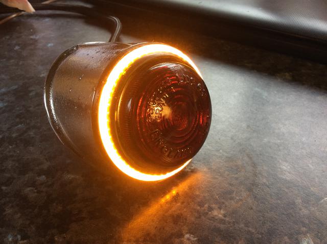
Here is my prototype of a very none pc take on TF tail lights. The LED ring replaces the chrome trim ring after slicing off some of the rubber. It’s stuck on with silicone.
When you identify the earth wire poke the strands through a bullet connector and spread them back around it and they will fit quite well into the ‘grounding’ tube or you can buy a ‘plug’ to solder on. Your other two wires will be a 50/50 bet on brake/flasher and tail light.
I had to run two extra wires in my new harness so I could operate the separate amber indicator. They will also be part of a hazard light system. The tail/brake bulb is now LED and the electronic flasher relays have a built in ‘click’.
At least your wires have some colour coding, my harness came in a bucket. All the wires were yellow and all of the terminals had been cut off....
Attachments:
D06C4183-5D70-4BAA-8E87-386D91174540.jpeg 39.2 KB

MGTF1500 Ardeche France
Thierry SUCHIER
|
Oct 17, 2017 02:10 AM
Top Contributor
Joined 7 years ago
5,563 Posts
|
Hello Chris,
Is it possible to have more detail on this new installation?
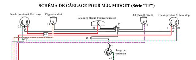
I had thought of adding two turn signals separated from the brake lights using wires 14 and 15.
I just had to add a green and purple wire for the brake lights.
But the idea of this circle led around the stop lights for the turn signals is interesting! These circles would prevent me from adding these blinking globes.
What are the parts for electronic flash relays that have a "click"?
Best regards, Thierry l'Ardéchois
Is it possible to have more detail on this new installation?
I had thought of adding two turn signals separated from the brake lights using wires 14 and 15.
I just had to add a green and purple wire for the brake lights.
But the idea of this circle led around the stop lights for the turn signals is interesting! These circles would prevent me from adding these blinking globes.
What are the parts for electronic flash relays that have a "click"?
Best regards, Thierry l'Ardéchois
Attachments:
Détail cablâge clignotants.jpg 18.2 KB
 |
Oct 17, 2017 02:27 AM
Top Contributor
Joined 11 years ago
2,198 Posts
|
|
Oct 17, 2017 02:45 AM
Joined 9 years ago
600 Posts
|
|
Bonjour Thierry,
In the original diagram 14 and 15 are connected to the brake lights and use the “direction indicator relay” to make them flash, I no longer use this relay. There were no separate clignotant lamps. I had to add “22” wires for the brakes.
The LED rings were found on eBay and are 70mm outside diameter and about 63 inside. The wires are drilled through the rubber mounts and the plinth then into the rubber tube. They are not + earth so had to be connected ‘backwards’.
The relays (I use a second one for the hazard lights) came from “classiccarleds.co.uk” part number CF13APL-R-C, 3P 12v LED Flasher, Positive Earth. The P lead goes to the green light on the dash (another LED), X to - ve supply and L to the switch.
Bonne chance,
Chris
|
MGTF1500 Ardeche France
Thierry SUCHIER
|
Oct 18, 2017 01:09 AM
Top Contributor
Joined 7 years ago
5,563 Posts
|
Forums 
Having trouble posting or changing forum settings?
Read the Forum Help (FAQ) or contact the webmaster
