
MGB & GT Forum
Test 1968-1971 MGB Tach outside of dash
Posted by ChuckoldNavy53


 |
Topic Creator (OP)
Sep 17, 2014 06:30 PM
Joined 12 years ago
679 Posts
|
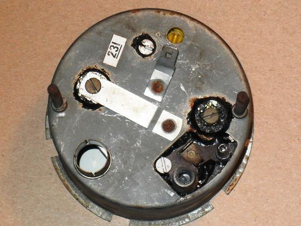
In an earlier post I was looking for a tach (part number RVI 1433/00) for 1969 MGB. Thanks to the help from members of the site. I was contacted by a gentleman who sent me one at a fair price. I received the part today and it looks exactly as advertized. Before I pull the old one I would like to hook it up and test it and at the same time set the tach so it's accurate, since I have a calibrated dwell/tach meter. Please look at the attached picture, the light hookup and the center ground post are clear. The alignment screw is clear. But there are three plugs in an indented area that I'm not sure of the connections. One has to be to the coil. But I'm not sure of which one and the other two I'm not sure about. I know I can just pull the old one and install the new to me version and see what happens. But getting under the dash is something I need to minimize. Anyone who can identify the other connections I would appreciate it.
I have the autozone wiring diagrams, but it doesn't address these connections.
Thanks;
Chuck
I have the autozone wiring diagrams, but it doesn't address these connections.
Thanks;
Chuck
Attachments:
distributor back 001.JPG 47 KB
 |
Sep 17, 2014 07:13 PM
Joined 10 years ago
1,071 Posts
|
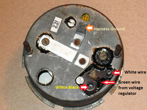
The RVI tach works by sensing the amount of times per minute current between the bullet terminals (White wire and white black) is broken. In order to test the gauge you will need to find a way to connect and break the signal 4009 (100 rpm) to 320,000 (8000 rpm) times per minute. A signal generator would work the best for this. I believe the green pole would need 10 volts from the voltage regulator of course the ground terminal is self explanatory.
Edited 1 time(s). Last edit at 2014-09-17 07:15 PM by MGJared.
Edited 1 time(s). Last edit at 2014-09-17 07:15 PM by MGJared.
Attachments:
RVI Tach.png 396 KB
 |
Sep 17, 2014 07:20 PM
Joined 17 years ago
2,833 Posts
|
As you noticed in the schematic, the tach in those years ran in series between the positive coil terminal and the ignition switch. So the first thing to note is that if you remove or disable the one currently in your dash, your car wont start.
The connections under the dash look vaguely like a male and female bullet connector. They're designed to plug into each other if you pull the tach so that power makes it to the coil and you can start the car without it.
If I were to try to test under the hood, I would add the new tach in series also on the same line. I'd get a pair of alligator clip leads, pull the white wire from the coil, attach one clip from that wire to one side of the tach, and take the other lead and attach one side from the other side of the tach to the coil. You'll also need to give the tach 12 volts on the terminal between the bullets from any of the sources nearby underhood.
__________________________
1970 MGB Black Label OD, APT VP12, Fidanza Flywheel, Flowspeed Head, Hilton AUD405 HS4 SU's, Schlemmerized Distributor, Pertronix Ignition, Saturn Alternator, 15" Dayton Wire Wheels, Falken ZE 912's, Falcon Big Bore
1972 MGB GT Blue Label OD, APT VP14, Fidanza Flywheel, Flowspeed Head, HIF SU's, Schlemmerized Distributor, Points Ignition, Saturn Alternator, 15" GC360 Wheels, Falken ZE-950s, Peco Exhaust, Frontline Costello front valance
Edited 1 time(s). Last edit at 2014-09-17 07:22 PM by GeeMoo.
|
|
Sep 17, 2014 07:23 PM
Joined 17 years ago
2,833 Posts
|
In reply to # 2800034 by MGJared
...I believe the green pole would need 10 volts from the voltage regulator of course the ground terminal is self explanatory.
I'm pretty sure the tach gets power from the 12 volt side of the stabilizer.
__________________________
1970 MGB Black Label OD, APT VP12, Fidanza Flywheel, Flowspeed Head, Hilton AUD405 HS4 SU's, Schlemmerized Distributor, Pertronix Ignition, Saturn Alternator, 15" Dayton Wire Wheels, Falken ZE 912's, Falcon Big Bore
1972 MGB GT Blue Label OD, APT VP14, Fidanza Flywheel, Flowspeed Head, HIF SU's, Schlemmerized Distributor, Points Ignition, Saturn Alternator, 15" GC360 Wheels, Falken ZE-950s, Peco Exhaust, Frontline Costello front valance
|
|
Sep 17, 2014 07:27 PM
Joined 17 years ago
2,833 Posts
|
Here's a (dusty) shot of the white wires connected to the tach and their molded bullets.
__________________________
1970 MGB Black Label OD, APT VP12, Fidanza Flywheel, Flowspeed Head, Hilton AUD405 HS4 SU's, Schlemmerized Distributor, Pertronix Ignition, Saturn Alternator, 15" Dayton Wire Wheels, Falken ZE 912's, Falcon Big Bore
1972 MGB GT Blue Label OD, APT VP14, Fidanza Flywheel, Flowspeed Head, HIF SU's, Schlemmerized Distributor, Points Ignition, Saturn Alternator, 15" GC360 Wheels, Falken ZE-950s, Peco Exhaust, Frontline Costello front valance
|
|
Sep 17, 2014 07:43 PM
Joined 17 years ago
2,833 Posts
|
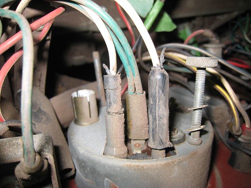
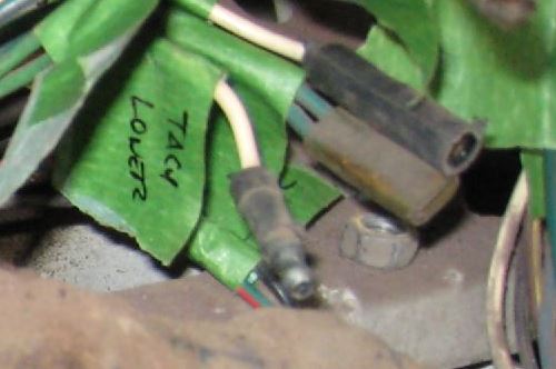
...and here's a shot of the connectors on the harness with the gauge disconnected:
__________________________
1970 MGB Black Label OD, APT VP12, Fidanza Flywheel, Flowspeed Head, Hilton AUD405 HS4 SU's, Schlemmerized Distributor, Pertronix Ignition, Saturn Alternator, 15" Dayton Wire Wheels, Falken ZE 912's, Falcon Big Bore
1972 MGB GT Blue Label OD, APT VP14, Fidanza Flywheel, Flowspeed Head, HIF SU's, Schlemmerized Distributor, Points Ignition, Saturn Alternator, 15" GC360 Wheels, Falken ZE-950s, Peco Exhaust, Frontline Costello front valance
 Abbotsford, BC, Canada
Sign in to contact
|
Sep 17, 2014 08:00 PM
Top Contributor
Joined 15 years ago
3,602 Posts
|
|
|
Sep 17, 2014 08:16 PM
Joined 17 years ago
2,833 Posts
|
In reply to # 2800084 by jewar
Wouldn't it be easier to take the old one out and just leave the new one hanging in place and try it. Tach isn't that hard to get out, probably harder to put back in.
John
John
That's what I would do too John. (but that didn't meet the criteria in the title
 )
)
Chuck: Maybe it would help to know that you only have to undo (and re-attach) the two thumbscrews from under/behind the dash. Once the gauge is loose, you can pull it out connections and all far enough to disconnect and reconnect everything in an upright and sane position.
__________________________
1970 MGB Black Label OD, APT VP12, Fidanza Flywheel, Flowspeed Head, Hilton AUD405 HS4 SU's, Schlemmerized Distributor, Pertronix Ignition, Saturn Alternator, 15" Dayton Wire Wheels, Falken ZE 912's, Falcon Big Bore
1972 MGB GT Blue Label OD, APT VP14, Fidanza Flywheel, Flowspeed Head, HIF SU's, Schlemmerized Distributor, Points Ignition, Saturn Alternator, 15" GC360 Wheels, Falken ZE-950s, Peco Exhaust, Frontline Costello front valance
 |
Sep 18, 2014 12:47 AM
Top Contributor
Joined 20 years ago
20,131 Posts
|
I have driven the tach on the test bench - but it is trickier than you might think. Since (as Jared pointed out) the RVI tach senses current, you need more than just a signal generator to drive it. I used a signal generator into a power amplifier in series with some resistors (I think I used about 10 ohm 25 watt power resistors). I also found that the tach is somewhat sensitive to the waveform shape, so it was trickier to calibrate than you might think.
And, to clarify another point, the tach gets its power from 12v, not from the instrument regulator.
If you really want to test it out of the dash, simply unhook the power wire that goes to the coil, connect it to the white lead on the tach. Then connect the white-black (this is from memory) terminal on the tach to the coil. Ground the tach and supply 12v to the power terminal. It should then read. But, I really think it is easier just to hook it up at the dash.
Terry Ingoldsby
terry.ingoldsby@DCExperts.com
|
|
Topic Creator (OP)
Sep 18, 2014 05:24 AM
Joined 12 years ago
679 Posts
|
I'm sure I can handle testing it now. Since as you said all I need to do is to remove the thumb screws to slide it out, I should be able to handle it. Again I appreciate all the detailed information and help. You know 20 years ago I would tear an engine down and overhaul it in a couple of weekends and side mechanic work helped pay for the down payment on my house. No not going to go there, just time and miles catching up with me. Take care and I'll let you know how it works out.
Thanks for the great information gentlemen;
Chuck
Thanks for the great information gentlemen;
Chuck

lil.red.roadster
Bernie Anderson
|
Sep 18, 2014 07:59 AM
Joined 11 years ago
1,294 Posts
|
A reasonable rule of thumb in electrics is that if the wire is live then the connector (on the wire) is 'female'.
so in this case the white from ignition switch goes to the 'male' terminal and the white/black being the non power side goes to the 'female' connector on the Tachometer.
Bernie
Bernie
"discere mutari est"
Wiring Diagrams: http://www.advanceautowire.com/mgb.pdf
Paul Hunts very useful site: http://www.mgb-stuff.org.uk
Manual for download: http://www.geomatique-liege.be/MGJP/DocumentsPDF/MGB_Workshop_Manual.pdf
UK MoT guide: https://www.gov.uk/government/uploads/system/uploads/attachment_data/file/518634/mot-inspection-manual-for-class-3-4-5-and-7-vehicles.pdf
Some basic guides: http://www.howacarworks.com/
1970 Roadster (First Reg July 10 1970). Std exhaust (Bell SS) AFAIK rest is bog standard
|
Abbotsford, BC, Canada
Sign in to contact
|
Sep 18, 2014 10:16 AM
Top Contributor
Joined 15 years ago
3,602 Posts
|
Chuck:
If you have wrenched for a living you will have the feel for it. Just like in Greg's picture thumb wheel nut on each side, under the nut will be a spacer that goes over the threads, might be a wire with eyelet over the threads as well for a ground. Pull that off and push tach forward from behind, when you can grab it pull it out.
John
|
|
Sep 18, 2014 10:48 AM
Joined 10 years ago
1,071 Posts
|
In reply to # 2800046 by GeeMoo
I'm pretty sure the tach gets power from the 12 volt side of the stabilizer.
In reply to # 2800034 by MGJared
...I believe the green pole would need 10 volts from the voltage regulator of course the ground terminal is self explanatory.
I'm pretty sure the tach gets power from the 12 volt side of the stabilizer.
You are probably correct on that one. I'll have to get my tester out the next time. I get in there.
|
|
Sep 18, 2014 11:05 AM
Joined 10 years ago
1,071 Posts
|
In reply to # 2800283 by ChuckoldNavy53
I'm sure I can handle testing it now. Since as you said all I need to do is to remove the thumb screws to slide it out, I should be able to handle it. Again I appreciate all the detailed information and help. You know 20 years ago I would tear an engine down and overhaul it in a couple of weekends and side mechanic work helped pay for the down payment on my house. No not going to go there, just time and miles catching up with me. Take care and I'll let you know how it works out.
Thanks for the great information gentlemen;
Chuck
Thanks for the great information gentlemen;
Chuck
Keep in mind you wont be able to get the points to move with out some way of generating a frequency on the white circuit. If all goes wrong let me know I have several RVI tachs in my parts storage.
|
|
Topic Creator (OP)
Sep 18, 2014 02:22 PM
Joined 12 years ago
679 Posts
|
Forums 
Having trouble posting or changing forum settings?
Read the Forum Help (FAQ) or contact the webmaster
