
MG Engine Swaps Forum
Hazard SW Wiring
Posted by 1744


 |
Topic Creator (OP)
Jul 29, 2014 03:46 PM
Top Contributor
Joined 17 years ago
6,652 Posts
|
I am a bit confuse when it comes to simple electrical wiring, I really do not like wiring, but I have to do it.
I am entering a Rally with my MGB and it is required to have a working Hazard lights as per their safety requirements, I had to fix the dip light sw since it is also required,
The dilema I am having with the hazard SW wiring is the two green wires coming from the SW # 7 and 8 both green.
# 7 green wire goes to the flasher unit and turn signal SW. # 8 in the schematic shows the green wire going to the instrument voltage stabilizer.
Question; 1) does # 8 needed, I am not using the voltage stabilizer with my gauges, it was discarded when the new wiring kit was installed a few years ago.
I appreciate any information.
It is our attitude that will determine the outcome
Member Services:
MG Classic Conversions V6. Wilwood brake dealer.
 |
Jul 29, 2014 04:19 PM
Joined 15 years ago
2,471 Posts
|
Bill, I am looking at the Advanced Auto wire schematic Diagram 17. Is that the diagram you are looking at?.
It looks like pin 8 supplies power to the turn signal flasher when the hazard switch is off. It runs to the unregulated side of the instrument voltage regulator. You could hook it to any switched 12v power lead.
The power to the hazard flasher is supplied by the brown wire.
Quis custodiet ipsos custodes?
Edited 3 time(s). Last edit at 2014-07-29 04:33 PM by lars49.
 |
Jul 29, 2014 07:22 PM
Top Contributor
Joined 18 years ago
2,306 Posts
|
|
|
Topic Creator (OP)
Jul 29, 2014 07:34 PM
Top Contributor
Joined 17 years ago
6,652 Posts
|
Larry, thank you for your input.
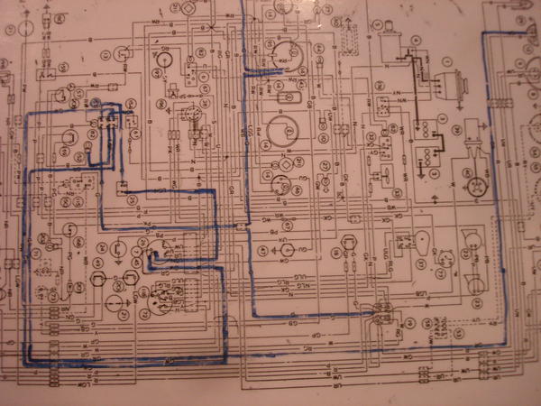
What I am using is the MGB diagram, using the stock SW which has 6 leads.
This is what I am using, a large MGB wiring diagram cover in plastic so that I can mark and erase as needed.
Easier for me to follow the wires.
The colors are # 1 Green/white---- To the turn signal sw
#2 Green/red ---to turn signal left front, not the turn signal sw
#3 light green/brown------to the flasher
#4 light green/purple------hazard light on panel
#5 non-existence same as # 6
#7 green-------to turn sw
# 8 green------to power 12v
Confuse about #2 wire shows going directly to the turn lamp.
#7 and #8 both green wires.
# 154 in the diagram is the flasher and # 67 is a fuse.
It is our attitude that will determine the outcome
Edited 1 time(s). Last edit at 2014-07-29 07:38 PM by 1744.
Member Services:
MG Classic Conversions V6. Wilwood brake dealer.
Attachments:
Hazar wireing diagram 001.jpg 53.9 KB
 |
Jul 29, 2014 08:03 PM
Top Contributor
Joined 19 years ago
15,771 Posts
|
|
|
Jul 30, 2014 01:06 PM
Joined 15 years ago
2,471 Posts
|
Bill,
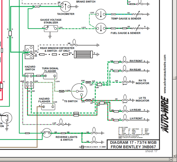
Here is a cutout of Dan's schematic. Maybe this will clear things up.
When the hazard switch is on:
When the hazard switch is off:
Quis custodiet ipsos custodes?
Edited 3 time(s). Last edit at 2014-07-30 01:34 PM by lars49.
Here is a cutout of Dan's schematic. Maybe this will clear things up.
When the hazard switch is on:
- Pin 5, which supplies power to the turn signal flasher, is disconnected
- Pin 4 is directed to the hazard lamp indicator
- Pin 3 is connected to pins 1 & 2, which direct the pulses of the hazard flasher to the turn signal lamps.
When the hazard switch is off:
- Pins 1, 2, 3, & 4 are disconnected.
- Pins 5 & 6 are connected and supply power to the turn signal flasher.
Quis custodiet ipsos custodes?
Edited 3 time(s). Last edit at 2014-07-30 01:34 PM by lars49.
Attachments:
hazard.png 163.9 KB
|
|
Topic Creator (OP)
Jul 31, 2014 12:40 PM
Top Contributor
Joined 17 years ago
6,652 Posts
|
Much better schematic than the factory one. Many thanks to you and Dan.
I am sure it works and it will be done this weekend.
Again thank you very much.
It is our attitude that will determine the outcome
I am sure it works and it will be done this weekend.
Again thank you very much.
It is our attitude that will determine the outcome
Member Services:
MG Classic Conversions V6. Wilwood brake dealer.
Forums 
Having trouble posting or changing forum settings?
Read the Forum Help (FAQ) or contact the webmaster
