
MGB & GT Forum
Dynamo vs alternator query
Posted by ozieagle


 Geelong Victoria, Australia
Sign in to contact
|
Topic Creator (OP)
Apr 24, 2014 03:56 PM
Top Contributor
Joined 13 years ago
15,846 Posts
|
Hi,
I've recently been studying how dynamos and alternators work, to decide whether to upgrade to an alternator (I will).
One thing I found is that dynamos have a current limiting function, in the control box, but there doesn't appear to be an equivalent limit in alternators. How is the max current limited in an alternator? Or are they built with such a high capacity that one couldn't possibly ever reach the limit?
Herb
 Philly 'burbs, PA, USA
Sign in to contact
|
Apr 24, 2014 04:47 PM
Top Contributor
Joined 14 years ago
26,261 Posts
|
Alternators require a voltage regulator, just as generators. Neither alternators nor generators know the state of charge of the battery and current draw by various accessories, so they just put out as much as they can, and this output tends to increase with engine/alternator/generator speed. It's the voltage regulator that serves as the spigot and determines how much of the alternator/generator's output to allow to pass into the vehicle's electrical system. In most modern alternators the voltage regulator is built into the alternator housing, but it's still there...
Dick
Errabundi Saepe, Semper Certi
(Often wrong, but always certain)
Dick
Errabundi Saepe, Semper Certi
(Often wrong, but always certain)
|
Geelong Victoria, Australia
Sign in to contact
|
Topic Creator (OP)
Apr 24, 2014 05:41 PM
Top Contributor
Joined 13 years ago
15,846 Posts
|
Thanks Dick,
I know all that, but dynamo control boxes actually have a current sensing cutout, that kills the field when current becomes excessive. Alternators have a voltage regulator, but I can't see how the current is sensed and controlled.
Herb
I know all that, but dynamo control boxes actually have a current sensing cutout, that kills the field when current becomes excessive. Alternators have a voltage regulator, but I can't see how the current is sensed and controlled.
Herb
 |
Apr 24, 2014 06:29 PM
Top Contributor
Joined 12 years ago
6,684 Posts
|
|
|
Apr 24, 2014 06:36 PM
Top Contributor
Joined 12 years ago
6,684 Posts
|
 |
Apr 24, 2014 07:06 PM
Top Contributor
Joined 17 years ago
10,944 Posts
|
FWIW, I'm sticking with my generator because it's **** simple and I can fix it if/when it goes bad.
 • The secret to creativity is knowing how to hide your sources.
• To the intelligent person, life appears infinitely mysterious, but the stupid have an answer for everything.
First rule of forum debate:
• My opinion becomes truth if I can find one other person, on the Internet with the same opinion. It is 'chiselled in stone" if I find two!
• To the intelligent person, life appears infinitely mysterious, but the stupid have an answer for everything.
First rule of forum debate:
• My opinion becomes truth if I can find one other person, on the Internet with the same opinion. It is 'chiselled in stone" if I find two!
|
Geelong Victoria, Australia
Sign in to contact
|
Topic Creator (OP)
Apr 24, 2014 08:50 PM
Top Contributor
Joined 13 years ago
15,846 Posts
|
I don't know if I'm not making myself clear or whether anyone actually reads my posts.
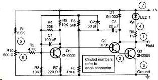
What I'm trying to find out is how the CURRENT in an alt is controlled, not the voltage. I know all about the field being regulated to give the required output, in both dynamos and alts. If you look at pic 1, it's a typical circuit of an alternator regulator. Note that there is nothing in there that measures current.
Now the next pic is of an electromechanical dynamo control unit. Notice that there is a relay in there that specifically controls the current. No such thing in an alternator.
Herb
 |
Apr 24, 2014 09:09 PM
Joined 16 years ago
3,155 Posts
|
I hear ya, Herb. Let me take a run at it.
I'm a mechanical guy, ME degree, not an EE degree, so I convert electrical stuff to hydraulic stuff. So bear with me.
Current = flow - let's call that gallons per minute (gpm)
Voltage = pressure, or head. Say in feet.
Alternator = a pump.
Think of the energy potential of the system as a barrel. The pump regulated for a certain pressure. Maybe the pressure equivalent of a pipe, or barrel of water 14 feet tall.
The pump is sized to maintain that 14 feet of pressure, up to a certain flow of gpm. If there are a lot of holes, or taps, at the bottom of the barrel, of various sizes - the question is, can the pump keep up that 14 feet of pressure if they're all open? Or just some of them? If it can't - then the 14 feet of pressure starts to drop. Maybe we have a 36 gpm pump, in which case if the taps are sized such that when they're all open, at 14 ft of pressure, the flow can't exceed 36 gpm - we're good.
Note that if all the taps are closed, there is no flow. Our pump shuts off, because once it hits that 14 feet of pressure, the regulator shuts it off until there's some demand for flow.
Back to electricity. The key concept is, if there is no demand on the system - no lights, no battery to be charged, no motors running, no ignition (ok, there's always that if the alternator is running) - then there is no current. There's still 14 volts of 'pressure', but there isn't any significant load on the alternator. The alternator doesn't create demand - the electrical devices in the car do that. All it does it try to meet the demand the devices present to it. No demand = no current.
Thus, current is not regulated. Only voltage is.
OK, now all the EE's in the audience can correct this.
Documenting my project in my journal at https://www.mgexp.com/home#journal
 |
Apr 24, 2014 09:53 PM
Joined 12 years ago
16 Posts
|
I'll give it a try, Electricity follows the equation V=IR. Voltage = I( current) X R( Resistance). With a little manipulation you find that Current is determined by the Voltage divided by the Resistance V/R = I. So, in a circuit the current traveling trough a circuit with a 14 volt potential is always going to be determined by the resistance in the circuit. So with the resistance fixed in a circuit (windings in the dynamo, inherent resistance in the battery and other connected devices) the current is going to be determined by the voltage which is controlled by the voltage regulator.
That is as much as I remember from my three years in EE in the early 1980's
Alan
That is as much as I remember from my three years in EE in the early 1980's
Alan
|
|
Apr 24, 2014 11:10 PM
Top Contributor
Joined 12 years ago
6,684 Posts
|
This is hard for me to articulate.
But the current output is controlled by the load. And the field voltage is going to
regulate current output.
The windings are going to limit the output. A 105 amp alternator is never going to produce more than 105 amps.
Using a Sun VAT 40 machine I have never been able to hit the maximum amp output under full load. It was usually about 85%.

tinkera123
Ian Bell
Melbourne, Victoria, Australia
Sign in to contact
|
Apr 25, 2014 12:00 AM
Joined 12 years ago
71 Posts
|
Hi Herb,
Yep, read all your Posts ..... and yes your question is clear. Voltage regulation, but no current limiting to protect coil windings etc from excessive heating etc ......
In the current regulator above, it would seem to me that the load current (or a sample) is passed through the relay coil. When the current is too high, the relay is triggered, turning off the current ..... my guess is that you have this figured out already.
Lots of modern equipment has current limiting devices built-in. An example ..... a sample of the load current is passed through a resistor; once the current reaches a certain level, the subsequent voltage drop across this resistor will turn off a transistor, which turns off the supply current ...... a simple current limiter.
Don't have the answer you need .... but is a good question. I will take a closer look at that circuit this evening.
Cheers,
Ian
|
Geelong Victoria, Australia
Sign in to contact
|
Topic Creator (OP)
Apr 25, 2014 02:18 AM
Top Contributor
Joined 13 years ago
15,846 Posts
|
OK, let's clarify things a bit.
I'm a trained electronics engineer, with substantial design experience, so electricity is not a black art. I understand how the regulators work to control VOLTAGE.
I agree with Ian, that in power supply units, there is a current sensing resistor in series with the load, that will limit the output current, but there is no such resistor in alt regulators. In fact the output current doesn't even flow through the regulator. The regulator purely controls the output voltage. I'm only talking about modern electronic regulators, not the electromechanical ones, adapted to alternators, which probably still have that current sensing relay.
As far as I can see, if you put a short across the output of the alt, it will try to maintain 14V across that short, at squillions of amps. What limits that output current, or does the alt continue to pump out amps till it melts?
I appreciate the hydraulics analogy, but if you speed up the pump, beyond its ratings, you could get extra flow, for a short while, which would give you the flow to all those extra taps.
One answer, that I can think of, is that the alt is designed to such accuracy, that the internal resistance is such that it automatically starts to drop the output voltage, at overload, even though the regulator is trying to increase the output. If so, why didn't they design the same into dynamos, instead of the extra expense of current sensing relays?
Another answer is that maybe the field design is finessed so fine that even flat out it can only generate its rated output. Again, why not with dynamos?
I was hoping that someone better versed in alt design might chip in.
Herb
|
Apr 25, 2014 04:28 AM
Joined 10 years ago
1,183 Posts
|
|
This is a WAG and probably wrong, but the generator voltage regulator coil opens the field contact to prevent overvoltage output. It's flapping like mad and with one flap too many doesn't open the circuit and the generator output goes bonkers. Being a willing soul, the generator gives its all and is rapidly approaching failure when the current sensing coil starts flapping to prevent burnout. Original alternators had mechanical regulators which appeared similar to generator regulators and may have had some form of current control. On the other hand, maybe the regulator is just trying to smooth the output and needs to regulate current and voltage to give a nicely formed square wave with all that brush commutating. In any case, it worked well for 40 some years.
 |
Apr 25, 2014 05:27 AM
Joined 13 years ago
460 Posts
|
Ok, first things first - An alternator IS a generator. 
I guess when you guys say "generator" you really mean "dynamo", which is another kind of generator.
The Workshop Manual always says dynamo, not generator, so why don't we ?
But, to get to the point,
As Richard neatly said, "The windings are going to limit the output."
Or, as expressed in various technical descriptions, "Current limiting is not provided in alternator regulators since the alternator magnetic structure inherently limits the maximum current that can be produced."
Jim
|
tinkera123
Ian Bell
Melbourne, Victoria, Australia
Sign in to contact
|
Apr 25, 2014 07:38 AM
Joined 12 years ago
71 Posts
|
Hi Herb,
Only thing that I can add are a couple of snippets on some web sites:-
Current limiting is not provided in alternator regulators since the alternator magnetic structure inherently limits the maximum current that can be produced.
-------------
Alternators can automatically current limit once the loading on the magnetic flux is exceeded that's why they don't need a current limiting relay
-------------
Alternators are self limiting on current. The field windings approach saturation near the rated current for a given alternator.
Hope this helps ....
Cheers,
Ian
Forums 
Having trouble posting or changing forum settings?
Read the Forum Help (FAQ) or contact the webmaster
