
MG Engine Swaps Forum
Camaro 3.4 is installed but look at this problem
Posted by limey222


limey222
Michael Cubbon
|
Topic Creator (OP)
Jul 3, 2015 02:30 PM
Joined 10 years ago
1,384 Posts
|
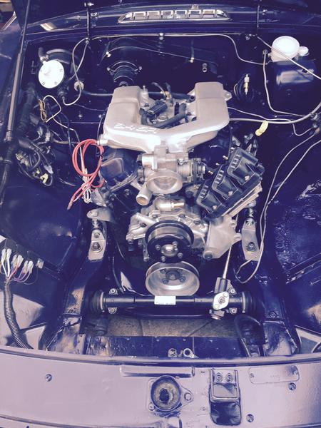
Have a look at these photos, the engine is as far back as I can get it. I have almost a 1/8: clearance between the crankshaft pulley and the steering rack except at one end where the larger rack tubing using is almost touching the pulley rim. I thought of putting washers under the rack brackets but it won't make much difference in the clearance because the angle is all wrong. The only thing I can think of is to remove the pullet and file a very localized 45 degree chamfer on the larger diameter tubing where the contact is almost being made.
Brian at BMCAutos tells me that a 1/8" clearance is sufficient and the multi goofed belt can be squeezed through the opening.
Any advice from this of you who have done this conversion wold be very helpful including photos. I don't think that machining off part of the pulley rim would be an option
Brian at BMCAutos tells me that a 1/8" clearance is sufficient and the multi goofed belt can be squeezed through the opening.
Any advice from this of you who have done this conversion wold be very helpful including photos. I don't think that machining off part of the pulley rim would be an option
Attachments:
FullSizeRender 3.jpg 55.9 KB
|
Townsend, TN, USA
Sign in to contact
|
Jul 3, 2015 04:04 PM
Joined 13 years ago
1,451 Posts
|
Michael -
Are you sure the crankshaft bolt is torqued all the way? I ask that because I seem to remember reading somewhere about that being a potential issue. I have about a half inch clearance on mine.
'73 MGB (Sold)
'69 MGB GT/V6 Conversion (Sold)
Victor TF 1800
'03 Jaguar XK8
Are you sure the crankshaft bolt is torqued all the way? I ask that because I seem to remember reading somewhere about that being a potential issue. I have about a half inch clearance on mine.
'73 MGB (Sold)
'69 MGB GT/V6 Conversion (Sold)
Victor TF 1800
'03 Jaguar XK8
|
limey222
Michael Cubbon
|
Topic Creator (OP)
Jul 3, 2015 04:16 PM
Joined 10 years ago
1,384 Posts
|
|
Jul 3, 2015 04:35 PM
Top Contributor
Joined 16 years ago
5,617 Posts
|
|
Loosen the transmission mounts and motor mounts and see if you can pry the motor back farther. The V6 swaps I've seen, the top bellhousing bolts are almost touching the firewall. Did you clearance(hammer or cut and weld) the corner of the footbox by the steering to allow it to go back further?
|
limey222
Michael Cubbon
|
Topic Creator (OP)
Jul 3, 2015 05:10 PM
Joined 10 years ago
1,384 Posts
|
Most of the required mods had been done by the previous owner who had fitted a German Ford 2.8 V6. If I push the motor any further back it will even hit the modified areas. I still have some clearance left on the corner of the footbox, maybe 3/16" - 1/4".
Brian at BMCAuto just called and suggested three options:
Elongate the holes in Bill Guzman's engine mounts to push the engine back a little more.
Put two washers between the two upper bolts that connect Guzman's brackets to the engine block on the driver's side to effectively push the motor slightly toward the passenger side of the engine compartment, thereby offsetting the pulley a little.
Elongate the hole that take the 1/2" studs in Bill's brackets to allow the engine to me back a little.
It's 100 degrees outside right now so investigation of these suggestions will have to wait.
In reply to # 3028756 by 260mgb
Loosen the transmission mounts and motor mounts and see if you can pry the motor back farther. The V6 swaps I've seen, the top bellhousing bolts are almost touching the firewall. Did you clearance(hammer or cut and weld) the corner of the footbox by the steering to allow it to go back further?

PLT-1
Paul G
|
Jul 3, 2015 08:03 PM
Joined 11 years ago
534 Posts
|
|
limey222
Michael Cubbon
|
Topic Creator (OP)
Jul 3, 2015 08:49 PM
Joined 10 years ago
1,384 Posts
|
As I said earlier in my posts, apparently you can do it if you have just over 1/8" clearance according to BMCAuto.
In reply to # 3028929 by PLT-1
I completely removed the firewall and tranny tunnel for my mock up.
It is my understanding there are thinner crank pulley's availible ?
How the hell are you gonna' get a belt on there ??...
It is my understanding there are thinner crank pulley's availible ?
How the hell are you gonna' get a belt on there ??...
|
Townsend, TN, USA
Sign in to contact
|
Jul 4, 2015 06:07 AM
Joined 13 years ago
1,451 Posts
|
Michael -
I just took a closer look at your first picture. Looks like the engine is indeed sitting too far to the driver's side. The large uprights on Bill's mounts pivot side to side, and from the picture it appears that they are sitting at the wrong angle - especially the driver's side. Almost like this: / /. Mine are more like this: / \. Before you do any surgery on the mounts, loosen the large horizontal bolt in each one and push the engine over; see if that helps. You'll probably have to loosen the nut at the top of the mounts as well.
Mickey
Edit: Attaching a picture. You can see that mine is sitting so that even if it were farther forward, the pulley wouldn't rub on the larger part of the steering rack tube. Tried to get a picture of the engine mount orientation, but too much stuff in the way. Hope this helps.
'73 MGB (Sold)
'69 MGB GT/V6 Conversion (Sold)
Victor TF 1800
'03 Jaguar XK8
Edited 1 time(s). Last edit at 2015-07-04 07:25 AM by Mickey Richaud.
Attachments:
PICT0760.JPG 31.1 KB
|
limey222
Michael Cubbon
|
Topic Creator (OP)
Jul 4, 2015 10:09 AM
Joined 10 years ago
1,384 Posts
|
Mickey
thanks for the input.
My photo is a bit deceptive, the mount on the passenger side is actually virtually vertical and just the drive's side is at an angle. So although I will try your suggestion I think I will end up with both mounts being \ / to some extentent. It seems to me that these cars all had a bit of variation in their construction, either that or 45 years of use, including some possible repaired accident damage may have changed things slightly.
it's very frustrating to get to this stage and then be held up from finishing things. However i know I have to fix the problem before moving on.
I believe that i will have to take some of the weight off the mounts by using a piece of wood and a trolley juack under the engine when loosening the 1/2" stud mounts prior to attempting to push the engine over more towrads the passenger side.
In reply to # 3029101 by Mickey Richaud
Michael -
I just took a closer look at your first picture. Looks like the engine is indeed sitting too far to the driver's side. The large uprights on Bill's mounts pivot side to side, and from the picture it appears that they are sitting at the wrong angle - especially the driver's side. Almost like this: / /. Mine are more like this: / \. Before you do any surgery on the mounts, loosen the large horizontal bolt in each one and push the engine over; see if that helps. You'll probably have to loosen the nut at the top of the mounts as well.
Mickey
Edit: Attaching a picture. You can see that mine is sitting so that even if it were farther forward, the pulley wouldn't rub on the larger part of the steering rack tube. Tried to get a picture of the engine mount orientation, but too much stuff in the way. Hope this helps.
 Abbotsford, BC, Canada
Sign in to contact
|
Jul 5, 2015 07:26 PM
Top Contributor
Joined 15 years ago
3,602 Posts
|
Mike:
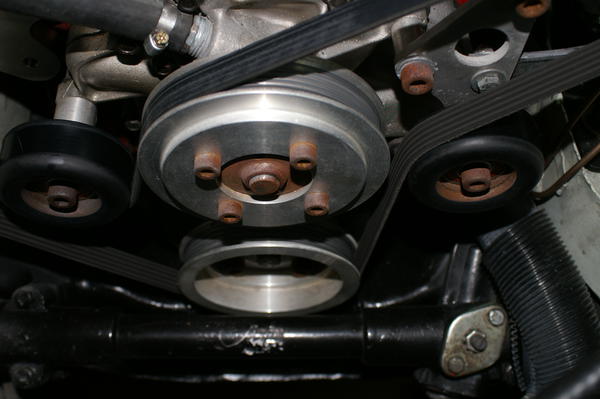
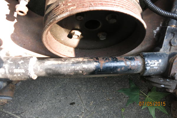
I have been following your progress, mine is unfinished but perhaps you can get some help from my pictures. I installed the original pulley on it to take the pictures, I will be using the CCE air condition kit when I am finished. I do have lot's of clearance with the rack and clearance with the cross member. Maybe more importantly the last 2 pictures show how far back my motor is.
The transmission mount is all bolted in place, I still have a bit of work to do on the steering column side. The project is a 70 GT.
Thanks,John
Attachments:
012.JPG 45.2 KB
|
limey222
Michael Cubbon
|
Topic Creator (OP)
Jul 5, 2015 08:45 PM
Joined 10 years ago
1,384 Posts
|
Thanks for the feedback. From your photo I an see an immediate different between your steering rack and mine. I assume that yours is a factory original whereas mine is a Moss replacement. If you look carefully you will see that on the right hand side, the larger diameter tube section is actually longer on mine which accounts for the encroachment into the vicinity of the pulley rim. If this was not happening on mine I would have a good 1/8" clearance which would suffice. The only way I will be able to increase the gap is to take Bill's lower brackets and elongate the back holes by 1/8" to push the assembly back further. I can't push my engine over towards the passenger side any further, the 1/2" engine mount studs are now in the / \ angular orientation which is good. Hard to tell from the angle of your photos but it looks like your pulley rim is about 1/4" off the rack.
In reply to # 3030332 by jewar
Mike:
I have been following your progress, mine is unfinished but perhaps you can get some help from my pictures. I installed the original pulley on it to take the pictures, I will be using the CCE air condition kit when I am finished. I do have lot's of clearance with the rack and clearance with the cross member. Maybe more importantly the last 2 pictures show how far back my motor is.
The transmission mount is all bolted in place, I still have a bit of work to do on the steering column side. The project is a 70 GT.
Thanks,John
|
Abbotsford, BC, Canada
Sign in to contact
|
Jul 5, 2015 11:34 PM
Top Contributor
Joined 15 years ago
3,602 Posts
|
Mike :
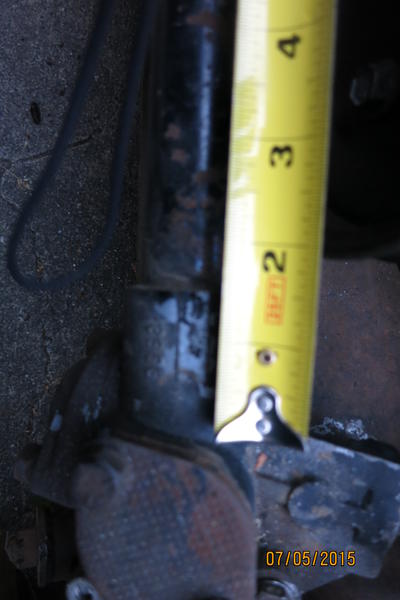
There is about 5/16 clearance between the rack and pulley. In picture 2, it is 3-5/8" from where the collar gets larger to the center of the back rack mounting bolt, hopefully that makes sense. Yes it is a original style rack. 4-1/8" from center of rack mounting bolt to pulley.
Hope that helps.John
There is about 5/16 clearance between the rack and pulley. In picture 2, it is 3-5/8" from where the collar gets larger to the center of the back rack mounting bolt, hopefully that makes sense. Yes it is a original style rack. 4-1/8" from center of rack mounting bolt to pulley.
Hope that helps.John
Attachments:
rack pictures 001.JPG 26.9 KB
|
Richardtherodder
Richard Mounce (Disabled) (Disabled)
|
Jul 6, 2015 01:44 AM
Joined 14 years ago
1,246 Posts
|
|
limey222
Michael Cubbon
|
Topic Creator (OP)
Jul 6, 2015 09:12 AM
Joined 10 years ago
1,384 Posts
|
I'm assuming thither is a difference between a 1969 and a 1974 models in this area, since there appears to be no physical way to achieve an inch using Bill Guzman's current install kit without elongating his original mounting holes to the extent that they break out the edge of the brackets that are bolted to the engine block or move the smaller hole in the lower brackets that houses the 1/2" stud without interfering with the stud mount. You would also have to mod the holes in the transmission mount as well.
In reply to # 3030497 by Richardtherodder
I have an inch of clearance between my rack and pulley in my '74 CB.
|
Jul 6, 2015 12:00 PM
Joined 13 years ago
43 Posts
|
|
Hi Michael,
I had the exact same problem as you and after searching for answers, I decided to get my pulley machined locally.
I had the CCE underdrive kit that was just barely touching the steering rack (same issue with the OEM pulley) so I took it to a local shop and had them remove some material from the front side of the pulley. I left the "how much" in the hands of the machinist because I trust him to know the minimum thickness needed to hold a belt on there more than I do.
Ever since then, no problems And yes, I tried loosening all the mounts and playing with the position and hammering the firewall and this and that and the other. I didn't want to use any washers or modify the CCE mounts since I was too scared it would change the engine/tranny angle and to be honest, here's a machine shop right next to my work. It took them under an hour and I was on my way.
I had the exact same problem as you and after searching for answers, I decided to get my pulley machined locally.
I had the CCE underdrive kit that was just barely touching the steering rack (same issue with the OEM pulley) so I took it to a local shop and had them remove some material from the front side of the pulley. I left the "how much" in the hands of the machinist because I trust him to know the minimum thickness needed to hold a belt on there more than I do.
Ever since then, no problems
And yes, I tried loosening all the mounts and playing with the position and hammering the firewall and this and that and the other. I didn't want to use any washers or modify the CCE mounts since I was too scared it would change the engine/tranny angle and to be honest, here's a machine shop right next to my work. It took them under an hour and I was on my way.Forums 
Having trouble posting or changing forum settings?
Read the Forum Help (FAQ) or contact the webmaster
